'antique' auto correcting analog clock 3D for print
6207 Views 1 Likes 0 Downloads Download the piece here from 3dforprint
https://youtu.be/XDOLTDkg-n0
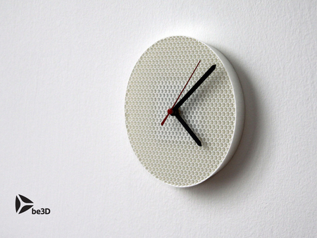
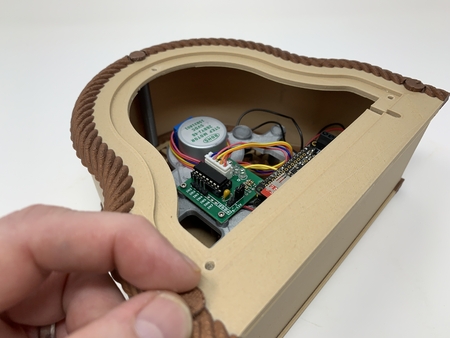
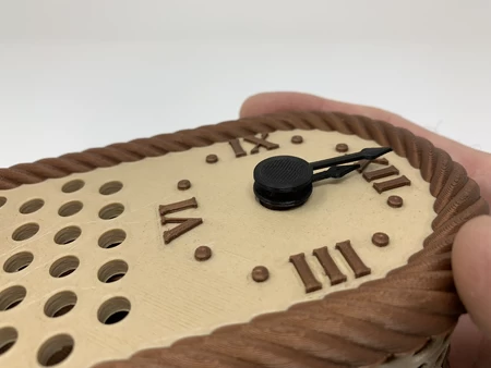
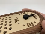
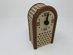
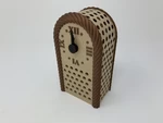
"'Antique' Auto Correcting Analog Clock" is an analog styled clock I de...signed to resemble a clock owned by my grandmother many years ago. Her clock had a wooden case with brass hardware and inner workings. This clock has a 3D printed case using wood and copper PLA for the clock case, details, and inner workings, and black PLA for the clock hands. Her clock used a spring driven windup mechanism, this clock uses an Adafruit Feather ESP 32, stepper motor and stepper motor controller to drive the clock hands at a rate of once per minute.
The clock software is designed to "home" the clock on power up or reset (e.g. rotate the clock hands to the 12:00 position) using a reed switch and magnets to detect the home position. Then using one of the numerous NTP clock servers to maintain time, the software rotates the clock hands to the correct time. The NTP clock server is polled by the software at the top of each hour and the time received from the NTP server is written into the ESP32 real time clock. At 12:00 (noon and midnight), if the clock is slow (detected by NTP time of 12:00, but the reed switch is not activated), the software will fast forward the clock to the 12:00 position (reed switch activated), then resume normal operation.
As usual, I probably forgot a file or two or who knows what else, so if you have any questions, please do not hesitate to ask as I do make mistakes in plenty.
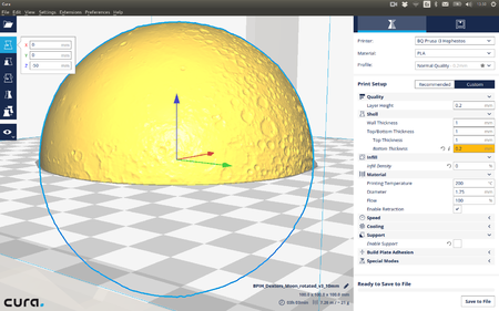
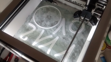
Designed using Autodesk Fusion 360, sliced using Cura 3.5.1, and printed in PLA on an Ultimaker 2+ Extended and an Ultimaker 3 Extended.
I purchased the following parts:
1) One Adafruit Feather ESP32 (Adafruit).
2) One set of Adafruit "slim"... female socket headers for the Feather ESP32 (Adafruit).
3) One stepper motor, controller and cables (TIMESETL 5pcs DC 5V Stepper Motor 28BYJ-48 + 5pcs ULN2003 Driver Board, online).
4) One reed switch (ORD2210V/20-25 AT, Mouser.com. These are very fragile, so I purchased 10).
5) Four 4mm by 10mm cap screws (local hardware store).
6) Four 4mm nuts (local hardware store).
7) Nine 3mm by 1.5mm neodymium magnets (local hobby shop).
8) One USB to ESP32 USB cable (Adafruit).
9) One lithium battery (3.7vdc, 1200mah, Adafruit). The battery is optional, see wiring.
I printed all 3D printed parts at .15mm layer height, the bolts and standoffs at 50% infill, the remaining parts at 20% infill, no support. The 3D printed parts include:
1) One "Axle Gear, Minutes To Hours.stl".
2) One "Back.stl".
3) Two "Bolt, 4mm.stl".
4) Seven "Bolt, 6mm by 8mm.stl".
5) One "Bolt, Holder, Switch, Reed.stl".
6) One "Cover.stl".
7) One "Door Knob.stl".
8) One "Door.stl".
9) One "Frame.stl".
10) One "Front, Dual Extrusion.3mf" or "Front.stl".
11) One "Gear, Hours.stl".
12) One "Gear, Minutes To Hours.stl".
13) One "Gear, Minutes.stl".
14) One "Hand, Hour.stl".
15) One "Hand, Minute.stl".
16) One "Holder, Switch, Reed.stl".
17) One "Rear, Dual Extrusion.3mf" or "Rear.stl".
18) Four "Spacer, Frame to PC Boards.stl".
19) Three "Standoff, Front to Rear.stl".
20) Four "Standoff, Frame to Rear.stl".
Prior to assembly, test fit and trim, file, sand, etc. all parts as necessary for smooth movement of moving surfaces, and tight fit for non moving surfaces. Depending on the colors you chose, your printer model and your printer settings, more or less trimming, filing and/or sanding may be required. Carefully file all edges that contacted the build plate, especially in and around the gear teeth, to make absolutely certain that all build plate "ooze" is removed and that all edges are smooth. I used small jewelers files and plenty of patience to perform this step. This model uses 4mm, 6mm and 8mm threaded components, so a tap and die set may be useful in cleaning the threaded parts.
Install the Reed Switch in the Reed Switch Holder.
A few notes about reed switches:
1) They are very fragile.
2) They are very fragile.
3) They are very fragile.
Well, you get the picture. I used a reed switch in this design because they require no power, and, well, I had a few left over from an earlier project. When bending the reed switch wires, always bend them using needle nose style pliers to hold the wire being bent. Never bend the wires at the glass as this will break the reed switch.
Begin by sliding the reed switch into "Holder, Switch, Reed.stl" to the position as shown. Hold the reed switch wire using needle nose pliers as shown, then bend the wire up and over the reed switch holder as shown. Repeat this process with the remaining reed switch wire.
Place this assembly in a safe place until wiring.
Assemble the Feather ESP32.
Assemble the Feather ESP32 using the "slim" female socket connectors as described here: https://learn.adafruit.com/adafruit-huzzah32-esp32-feather/assembly.
Wire the ESP32 to the Stepper Motor Controller and Reed Switch.
To wire the ESP32 to the stepper motor controller, I loosely attached the two boards, solder side up, to the gear side of "Frame.stl" using the four 4mm by 10mm cap screws and nuts (note there are only two cap screws, spacers and nuts per board), then:
1) Soldered a wire between the ESP32 pin 14 to stepper board pin IN4.
2) Soldered a wire between the ESP32 pin 32 to stepper board pin IN3.
3) Soldered a wire between the ESP32 pin 15 to stepper board pin IN2.
4) Soldered a wire between the ESP32 pin 33 to stepper board pin IN1.
5) Soldered a wire between the ESP32 pin GND to the stepper board pin "-".
6) Soldered a wire between the ESP32 pin "BAT" (for battery backup) or "USB" (non-battery use) to the stepper pin "+".
7) Soldered a wire between the ESP32 pin 27 to one wire of the reed switch.
8) Soldered a wire between the ESP32 pin GND to the remaining wire of the reed switch.
9) Using thick cyanoacrylate, glued the wires to the side of the reed switch holder to provide strain relief.
Assemble and Test the Clock Frame.
Attach both the ESP32 and stepper motor controller boards to the non-gear side of "Frame.stl", component side up, using four 4mm by 10mm cap screws, four "Spacer, Frame to PC Boards.stl" and four 4mm nuts as shown (note there are only two cap screws, spacers and nuts per board).
Attach the stepper motor to the frame assembly using the two "Bolt, 4mm.stl", then carefully rotate the stepper motor shaft to the vertical position as shown.
Press "Gear, Minutes.stl" fully onto the stepper motor shaft as shown.
Place "Gear, Minutes To Hours.stl" into position on the frame assembly orienting the vertical slot as shown, then secure in place with "Axle Gear, Minutes To Hours.stl". Do not over tighten.
Stack three of the neodymium magnets together, then press them into position on the flat side of "Gear, Hours.stl" as shown.
Position the reed switch assembly over the slot in the frame assembly, then secure in place with "Bolt, Holder, Switch, Reed.stl" as shown.
Wrap the excess stepper motor wires around the stepper motor, then plug the stepper motor connector into the connector on the stepper motor controller board.
Place the hour gear assembly onto the minute gear noting the alignment of the slot.
Once completed, all gear slots should be vertical which is the clock 12:00 position.
Next, power up the boards via USB and battery (if you wired the clock for USB and battery) or USB only (if you wired the clock for USB only), load the file "Clock.ino" into the Arduino environment, then perform the following:
1) Change the source code constant "HOME_SWITCH_CALIBRATE" to "true".
2) Change the source code variable "chSSID" to your wifi router SSID.
3) Change the source code variable "chPassword" to your wifi router password.
4) Download the code to the clock.
5) When downloaded, the clock minute gear should rotate 90 degrees counter clockwise, then move clockwise until the reed switch activates.
If the clock does not stop at 12:00:
1) If the clock is early, rotate or slide the reed switch holder away from the rotation of the hour gear magnets.
2) If the clock is late, rotate or slide the reed switch holder towards the rotation of the hour gear magnets.
3) Press the reset button on the ESP32.
4) If the clock stops at 12:00, you're done, but if not, back to step 1.
Once the reed switch holder is properly located, secure the reed switch holder into position using a small dot of thick cyanoacrylate glue.
Finally:
1) Change the source code constant "HOME_SWITCH_CALIBRATE" to "false".
2) Set the source code constant "TIME_ZONE" to your time zone (the offset from UTC to my time zone is -5).
3) Download the code to the clock.
4) Remove power.
Attach the Clock Frame to the Clock Rear.
Press three neodymium magnets into "Rear, Dual Extrusion.stl" or "Rear.stl". Make sure all magnets are oriented the same.
Thread the four "Standoff, Frame to Rear.stl" into the rear assembly as shown.
Position the frame assembly onto the four standoffs, then secure in place with four "Bolt, 6mm by 8mm.stl".
Assemble the Clock Front.
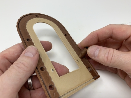
Thread the three "Standoff, Front to Rear.stl" into either "Front, Dual Extrusion.stl" or "Front.stl".
"Cover.stl" is optional, and if you decided to print it, press it into place in the slot around the front.
Assemble and Attach the Door.
Press the remaining three neodymium magnets into the holes in "Door.stl" making sure they align magnetically with the magnets in the rear assembly.
Thread "Door, Knob.stl" into the door assembly as shown.
Attach the USB cable to the ESP32, then route it out of the rear as shown.
Place the door assembly onto the rear assembly as shown.
Final Assembly.
If you will be using a battery, plug it into the ESP32 battery connector, then position it as shown and carefully slide the front assembly onto the rear assembly. Be very careful to not break the reed switch.
Secure the front assembly to the rear assembly using three "Bolt, 6mm by 8mm.stl" as shown.
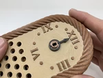
Press the hour hand fully onto the hour gear.
Press the minute hand fully into the minute gear.
Apply power to the clock. The clock will begin rotating clockwise to the 12:00 position, after which it will rotate via the shortest route to the NTP indicated time.
And that's how I printed and assembled "'Antique' Auto Correcting Analog Clock".
Hope you enjoy it!
Designer
Greg Zumwalt3d model description
An antique styled analog auto correcting clock.https://youtu.be/XDOLTDkg-n0
"'Antique' Auto Correcting Analog Clock" is an analog styled clock I de...signed to resemble a clock owned by my grandmother many years ago. Her clock had a wooden case with brass hardware and inner workings. This clock has a 3D printed case using wood and copper PLA for the clock case, details, and inner workings, and black PLA for the clock hands. Her clock used a spring driven windup mechanism, this clock uses an Adafruit Feather ESP 32, stepper motor and stepper motor controller to drive the clock hands at a rate of once per minute.
The clock software is designed to "home" the clock on power up or reset (e.g. rotate the clock hands to the 12:00 position) using a reed switch and magnets to detect the home position. Then using one of the numerous NTP clock servers to maintain time, the software rotates the clock hands to the correct time. The NTP clock server is polled by the software at the top of each hour and the time received from the NTP server is written into the ESP32 real time clock. At 12:00 (noon and midnight), if the clock is slow (detected by NTP time of 12:00, but the reed switch is not activated), the software will fast forward the clock to the 12:00 position (reed switch activated), then resume normal operation.
As usual, I probably forgot a file or two or who knows what else, so if you have any questions, please do not hesitate to ask as I do make mistakes in plenty.
Designed using Autodesk Fusion 360, sliced using Cura 3.5.1, and printed in PLA on an Ultimaker 2+ Extended and an Ultimaker 3 Extended.
3d model print parameters
Purchase, Print and Prepare the Parts.I purchased the following parts:
1) One Adafruit Feather ESP32 (Adafruit).
2) One set of Adafruit "slim"... female socket headers for the Feather ESP32 (Adafruit).
3) One stepper motor, controller and cables (TIMESETL 5pcs DC 5V Stepper Motor 28BYJ-48 + 5pcs ULN2003 Driver Board, online).
4) One reed switch (ORD2210V/20-25 AT, Mouser.com. These are very fragile, so I purchased 10).
5) Four 4mm by 10mm cap screws (local hardware store).
6) Four 4mm nuts (local hardware store).
7) Nine 3mm by 1.5mm neodymium magnets (local hobby shop).
8) One USB to ESP32 USB cable (Adafruit).
9) One lithium battery (3.7vdc, 1200mah, Adafruit). The battery is optional, see wiring.
I printed all 3D printed parts at .15mm layer height, the bolts and standoffs at 50% infill, the remaining parts at 20% infill, no support. The 3D printed parts include:
1) One "Axle Gear, Minutes To Hours.stl".
2) One "Back.stl".
3) Two "Bolt, 4mm.stl".
4) Seven "Bolt, 6mm by 8mm.stl".
5) One "Bolt, Holder, Switch, Reed.stl".
6) One "Cover.stl".
7) One "Door Knob.stl".
8) One "Door.stl".
9) One "Frame.stl".
10) One "Front, Dual Extrusion.3mf" or "Front.stl".
11) One "Gear, Hours.stl".
12) One "Gear, Minutes To Hours.stl".
13) One "Gear, Minutes.stl".
14) One "Hand, Hour.stl".
15) One "Hand, Minute.stl".
16) One "Holder, Switch, Reed.stl".
17) One "Rear, Dual Extrusion.3mf" or "Rear.stl".
18) Four "Spacer, Frame to PC Boards.stl".
19) Three "Standoff, Front to Rear.stl".
20) Four "Standoff, Frame to Rear.stl".
Prior to assembly, test fit and trim, file, sand, etc. all parts as necessary for smooth movement of moving surfaces, and tight fit for non moving surfaces. Depending on the colors you chose, your printer model and your printer settings, more or less trimming, filing and/or sanding may be required. Carefully file all edges that contacted the build plate, especially in and around the gear teeth, to make absolutely certain that all build plate "ooze" is removed and that all edges are smooth. I used small jewelers files and plenty of patience to perform this step. This model uses 4mm, 6mm and 8mm threaded components, so a tap and die set may be useful in cleaning the threaded parts.
Install the Reed Switch in the Reed Switch Holder.
A few notes about reed switches:
1) They are very fragile.
2) They are very fragile.
3) They are very fragile.
Well, you get the picture. I used a reed switch in this design because they require no power, and, well, I had a few left over from an earlier project. When bending the reed switch wires, always bend them using needle nose style pliers to hold the wire being bent. Never bend the wires at the glass as this will break the reed switch.
Begin by sliding the reed switch into "Holder, Switch, Reed.stl" to the position as shown. Hold the reed switch wire using needle nose pliers as shown, then bend the wire up and over the reed switch holder as shown. Repeat this process with the remaining reed switch wire.
Place this assembly in a safe place until wiring.
Assemble the Feather ESP32.
Assemble the Feather ESP32 using the "slim" female socket connectors as described here: https://learn.adafruit.com/adafruit-huzzah32-esp32-feather/assembly.
Wire the ESP32 to the Stepper Motor Controller and Reed Switch.
To wire the ESP32 to the stepper motor controller, I loosely attached the two boards, solder side up, to the gear side of "Frame.stl" using the four 4mm by 10mm cap screws and nuts (note there are only two cap screws, spacers and nuts per board), then:
1) Soldered a wire between the ESP32 pin 14 to stepper board pin IN4.
2) Soldered a wire between the ESP32 pin 32 to stepper board pin IN3.
3) Soldered a wire between the ESP32 pin 15 to stepper board pin IN2.
4) Soldered a wire between the ESP32 pin 33 to stepper board pin IN1.
5) Soldered a wire between the ESP32 pin GND to the stepper board pin "-".
6) Soldered a wire between the ESP32 pin "BAT" (for battery backup) or "USB" (non-battery use) to the stepper pin "+".
7) Soldered a wire between the ESP32 pin 27 to one wire of the reed switch.
8) Soldered a wire between the ESP32 pin GND to the remaining wire of the reed switch.
9) Using thick cyanoacrylate, glued the wires to the side of the reed switch holder to provide strain relief.
Assemble and Test the Clock Frame.
Attach both the ESP32 and stepper motor controller boards to the non-gear side of "Frame.stl", component side up, using four 4mm by 10mm cap screws, four "Spacer, Frame to PC Boards.stl" and four 4mm nuts as shown (note there are only two cap screws, spacers and nuts per board).
Attach the stepper motor to the frame assembly using the two "Bolt, 4mm.stl", then carefully rotate the stepper motor shaft to the vertical position as shown.
Press "Gear, Minutes.stl" fully onto the stepper motor shaft as shown.
Place "Gear, Minutes To Hours.stl" into position on the frame assembly orienting the vertical slot as shown, then secure in place with "Axle Gear, Minutes To Hours.stl". Do not over tighten.
Stack three of the neodymium magnets together, then press them into position on the flat side of "Gear, Hours.stl" as shown.
Position the reed switch assembly over the slot in the frame assembly, then secure in place with "Bolt, Holder, Switch, Reed.stl" as shown.
Wrap the excess stepper motor wires around the stepper motor, then plug the stepper motor connector into the connector on the stepper motor controller board.
Place the hour gear assembly onto the minute gear noting the alignment of the slot.
Once completed, all gear slots should be vertical which is the clock 12:00 position.
Next, power up the boards via USB and battery (if you wired the clock for USB and battery) or USB only (if you wired the clock for USB only), load the file "Clock.ino" into the Arduino environment, then perform the following:
1) Change the source code constant "HOME_SWITCH_CALIBRATE" to "true".
2) Change the source code variable "chSSID" to your wifi router SSID.
3) Change the source code variable "chPassword" to your wifi router password.
4) Download the code to the clock.
5) When downloaded, the clock minute gear should rotate 90 degrees counter clockwise, then move clockwise until the reed switch activates.
If the clock does not stop at 12:00:
1) If the clock is early, rotate or slide the reed switch holder away from the rotation of the hour gear magnets.
2) If the clock is late, rotate or slide the reed switch holder towards the rotation of the hour gear magnets.
3) Press the reset button on the ESP32.
4) If the clock stops at 12:00, you're done, but if not, back to step 1.
Once the reed switch holder is properly located, secure the reed switch holder into position using a small dot of thick cyanoacrylate glue.
Finally:
1) Change the source code constant "HOME_SWITCH_CALIBRATE" to "false".
2) Set the source code constant "TIME_ZONE" to your time zone (the offset from UTC to my time zone is -5).
3) Download the code to the clock.
4) Remove power.
Attach the Clock Frame to the Clock Rear.
Press three neodymium magnets into "Rear, Dual Extrusion.stl" or "Rear.stl". Make sure all magnets are oriented the same.
Thread the four "Standoff, Frame to Rear.stl" into the rear assembly as shown.
Position the frame assembly onto the four standoffs, then secure in place with four "Bolt, 6mm by 8mm.stl".
Assemble the Clock Front.
Thread the three "Standoff, Front to Rear.stl" into either "Front, Dual Extrusion.stl" or "Front.stl".
"Cover.stl" is optional, and if you decided to print it, press it into place in the slot around the front.
Assemble and Attach the Door.
Press the remaining three neodymium magnets into the holes in "Door.stl" making sure they align magnetically with the magnets in the rear assembly.
Thread "Door, Knob.stl" into the door assembly as shown.
Attach the USB cable to the ESP32, then route it out of the rear as shown.
Place the door assembly onto the rear assembly as shown.
Final Assembly.
If you will be using a battery, plug it into the ESP32 battery connector, then position it as shown and carefully slide the front assembly onto the rear assembly. Be very careful to not break the reed switch.
Secure the front assembly to the rear assembly using three "Bolt, 6mm by 8mm.stl" as shown.
Press the hour hand fully onto the hour gear.
Press the minute hand fully into the minute gear.
Apply power to the clock. The clock will begin rotating clockwise to the 12:00 position, after which it will rotate via the shortest route to the NTP indicated time.
And that's how I printed and assembled "'Antique' Auto Correcting Analog Clock".
Hope you enjoy it!