How i designed a 3d printed windup car using autodesk fusion 360. 3D for print

26239 Views 1 Likes 0 Downloads Download the piece here from 3dforprint
I've designed, 3D printed, assembled, tested and published quite a few PLA spring mo...tor floating pinion cars and demonstrators over the last few years, so why would I design, print, assemble, test and publish yet another one?
Well, "How I Designed a 3D Printed Windup Car Using Autodesk Fusion 360" includes a four part video series detailing how I designed this 3D printed windup car (with floating pinion drive) using Autodesk Fusion 360. And I've also included the Autodesk Fusion 360 cad file "Windup Floating Pinion Car.f3d" containing the completed design (familiarity with the Autodesk Fusion 360 environment is highly recommended, and if a discrepancy is found between the videos and the cad file, use the cad file).
So if you're interested in my design process for a PLA spring motor powered windup car with floating pinion drive, and / or wish to modify the design to create your own custom version, then this tutorial may indeed be of interest to you.
And if you're simply interested in 3D printing and assembling the car, I've included all STL files required to print the car, along with preparation and assembly instructions.
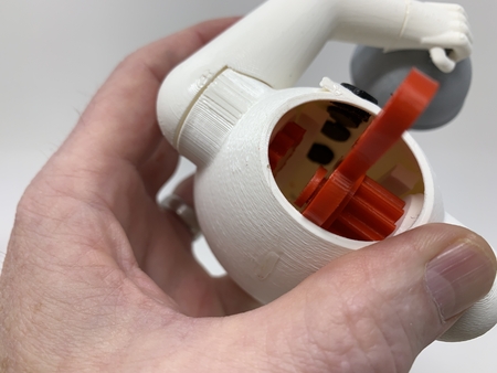
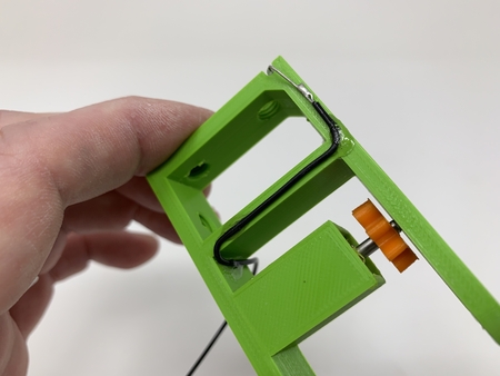
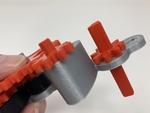
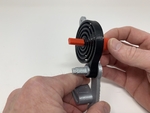
And finally, what's a floating pinion? In this design a floating pinion is a pinion gear that traverses a guide slot, engaging the PLA spring motor with the drive axle when spring energy is present, and disengaging the PLA spring motor from the drive axle when spring energy is depleted. By disengaging the PLA spring motor from the drive axle, the car is allowed to coast, as opposed to abruptly stopping, when spring energy is depleted providing a significant increase in travel distance.
And as usual, I probably forgot a file or two or who knows what else, so if you have any questions, please do not hesitate to ask as I do make plenty of mistakes.
Designed using Autodesk Fusion 360, sliced using Cura 4.0, and printed in PLA and Tough PLA on an Ultimaker 2+ Extended and an Ultimaker 3 Extended.
The spring motor consists of the "Knob.stl", "Spring.stl", "Pawl.stl" and "Gear, Pawl (24, 2.2).stl". The knob is used to wind the spring, and the pawl and pawl gear provide the ratchet mechanism for winding.
As with all components of this model, I design using what I call "sketch in place" which keeps the sketch in position with the extruded component for easier editing.
The pawl gear, as with all gears used in this model, was designed using a module of 2.2. There are only two gear sizes used in this model; twenty four and eight tooth. For a twenty four tooth gear, the pitch radius is ((24 * 2.2) / 2) or 26.4mm. For an eight tooth gear, the pitch radius is ((8 * 2.2) / 2) or 8.8mm. These dimensions will be used in the next step.
Designing the Gear Train.
Math, math and more math...
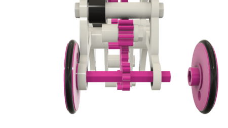
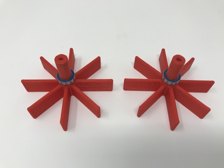
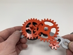
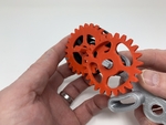
The gear train consists of the three gears "Gear, Compound ((24, 2.2), (8, 2.2)).stl", "Gear, Floating Pinion (8, 2.2).stl" and "Gear, Axle (8, 2.2).stl", that transfer the PLA spring motor energy to the drive axle.
As mentioned in the previous step, I used a module value of 2.2 for both the twenty four and eight tooth gears (in practice, when designing a gear train, it is best to use the same module for all gears in the gear train). To determine the spacing between a twenty four and eight tooth gear, the equation I use is:
((24 * 2.2) / 2) + ((8 * 2.2) / 2) + .4mm = 35.6mm.
This simple equation adds the pitch radius of the twenty four tooth gear to the pitch radius of the eight tooth gear, then adds .4mm for slight additional clearance between the gears to account for 3D printing variances (make sure your 3D printer is not over extruding, and don't forget to carefully remove the build plate side "ooze" from the gears using jewelers files or equivalent).
Similarly, the spacing between two eight tooth gears with a module of 2.2 is:
((8 * 2.2) / 2) + ((8 * 2.2) / 2) + .4mm = 18mm.
These two dimensions, 35.6mm and 18mm, are used in this video to space the gears in the gear train.
The total gear ratio from the PLA spring motor to the drive axle is 1:9 (drive to driven), using two gear stages of 1:3 each (e.g. (24 teeth / 8 teeth) = 3, and (3 * 3) = 9). This results in for each rotation of the spring motor, the drive axle will rotate nine times (which is an increase in rotational rate from the PLA spring motor to the drive axle, at the expense of a loss in torque). Thus with a wheel diameter of 47.5mm (as measured using a digital caliper with the O-Rings I used), the distance the car will travel under spring power is approximately (assuming zero traction and friction losses):
(pi * wheel diameter) * 1.25 * 9 = 1678.788574262046mm = 5.5 feet,
where:
1) (pi * wheel diameter) = wheel circumference = 149.2256510455152mm,
2) 1.25 is the number of winds of the PLA spring motor knob, hence the number of times the PLA spring motor will rotate (discounting friction loss and failure to remove the build plate "ooze"),
3) 9 is the total gear ratio from the PLA spring motor to the drive axle (again, drive to driven).
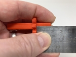
To test the math, I fully wound the PLA spring motor, held the car firmly on a smooth surface along side an extended tape measure, then moved the car forward by hand noting that the floating pinion gear indeed disengaged the PLA spring motor from the drive axle at exactly 5'6" (ok, math isn't that bad after all).
Finally, remember after the PLA spring motor energy is depleted, the floating pinion disengages the PLA spring motor from the drive axle allowing the car to coast. During testing, my cars coasted an additional 15 feet and more after the PLA spring motor energy was depleted.
Designing the Chassis.Whew, glad that math is over...
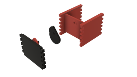
The chassis consists of the two frames, "Frame, Right.stl" and "Frame, Left.stl".
To gain additional ground clearance, in this video the gear train layout is modified, then the PLA spring motor and gear train components are used to assist with laying out the right frame.
With the right frame complete, the left frame is created by "projecting" the right frame profile, then modifying the various socket and crossmember profiles to allow mating of the two frame sides.
Designing the Axles and Wheels.
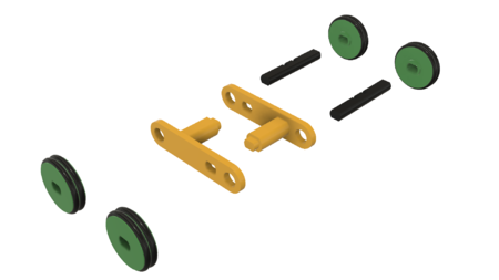
There are two unique axles "Axle, Gear, Floating.stl" and "Axle.stl", and one unique "Wheel.stl" designed in this step.
After centering the car assembly, the rear axle is designed and then copied and pasted to create the front axle.
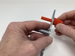
Next the floating pinion axle is designed and positioned
With the axle designs completed, the wheel is designed, then copied and pasted to create the remaining wheels.
I purchased eight "R-28" O-Rings (38mm ID, 3.5mm Section) for the "tires". These O-Rings fit tight on the w...heels, but slightly larger O-Rings may be used.
As mentioned, I've included all STL files with the components properly oriented for no support 3D printing. If you wish to create your own STL files from the included Autodesk Fusion 360 file "Windup Floating Pinion Car.f3d", remember to properly orient them on the build plate using your slicer prior to printing, and make sure to "hide" (e.g. "light bulb" off) both the O-Ring 1 and O-Ring 2 bodies of the Wheel component prior to creating the STL file for the Wheel component.
I printed the following quantities and parts at .15mm layer height with the infill percentage and materials as specified:
1) One "Axle, Gear, Floating Pinion (8, 2.2).stl", 50% infill, PLA.
2) Two "Axle.stl", 50% infill, PLA.
3) One "Frame, Left.stl", 100% infill, PLA.
4) One "Frame, Right.stl", 100% infill, PLA.
5) One "Gear, Axle (8, 2.2).stl", 50% infill, PLA.
6) One "Gear, Compound ((24, 2.2), (8, 2.2))", 50% infill, PLA.
7) One "Gear, Floating Pinion (8, 2.2).stl", 50% infill, PLA.
8) One "Gear, Pawl (24, 2.2).stl", 50% infill, PLA.
9) One "Knob.stl", 100% infill, PLA.
10) One "Pawl.stl, 100% infill, Tough PLA (PLA may be used but will provide less torque and longevity).
11) One "Spring.stl", 100% infill, Tough PLA (PLA may be used but will provide less torque and longevity).
12) Four "Wheel.stl", 50% infill, PLA.
Prior to assembly, I test fit and trimmed, filed, sanded, etc. all parts as necessary for smooth movement of moving surfaces, and tight fit for non moving surfaces. If you decide to make your own Windup Car, depending on the colors you chose, your printer model and your printer settings, more or less trimming, filing and/or sanding may be required. I carefully filed all edges that contacted the build plate to make absolutely certain that all build plate "ooze" was removed and that all edges were smooth. I used small jewelers files and plenty of patience to perform this step.
Assembly and Test.
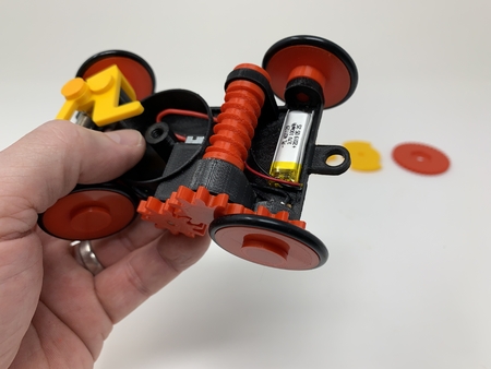
I assembled the car as follows (refer to the photographs for proper location and orientation of the various components):
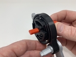
1) Slid "Knob.stl" into "Frame, Right.stl", making sure the knob rotated freely in the right frame.
2) Pressed "Spring.stl" onto "Knob.stl" while positioning the spring end over the crossmember on the right frame.
3) Pressed "Pawl.stl" onto "Knob.stl". This must be a tight fit for the Knob to remain in place.
4) Placed "Gear, Pawl (24, 2.2).stl" onto "Pawl.stl".
5) Placed "Gear, Compound ((24, 2.2), (8, 2.2)).stl" onto the crossmember on frame, right, making sure the gear rotated freely on the crossmember.
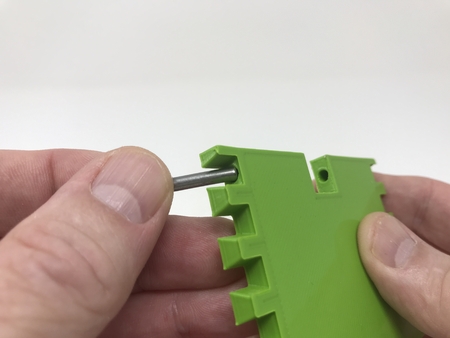
6) Pressed "Axle, Gear, Floating Pinion.stl" into "Gear, Floating Pinion (8, 2.2).stl" making sure the gear was centered on the axle. This must be a tight fit.
7) Placed the floating pinion gear assembly into the guide slot on frame, right, making sure the floating pinion gear assembly rotated and slid freely in the guide slot.
8) Pressed one "Axle.stl" into "Gear, Axle (8, 2.2).stl" such that the gear was 16.5mm from one end of the axle. This is the rear axle assembly and the gear must be a tight fit on the axle.
9) Placed the longer end of the rear axle assembly into the rear axle hole of frame, right making sure the axle assembly rotated freely in the frame.
10) Pressed "Frame, Left.stl" onto the frame, right assembly. This must be a tight fit.
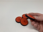
11) Placed the eight O-Rings onto the four "Wheel.stl" (two per wheel). This must be a tight fit to avoid slippage and thus energy loss.
12) Pressed two wheels onto the rear axle assembly such that the outer wheel surfaces were flush with the axle ends. This must be a tight fit, and must rotate freely.
13) Pressed the remaining "Axle.stl" into one of the remaining wheels such that the outer wheel surface was flush with the axle end. This must be a tight fit.
14) Slid this wheel assembly into the front axle hole in the frame assembly, making sure the wheel assembly rotated freely in the frame assembly.
15) Pressed the remaining wheel assembly onto the remaining axle end such that the outer wheel surface was flush with the axle end, and making sure the wheels and axle rotated freely in the frame assembly.
To test the car, hold "Gear, Compound ((24, 2.2), (8, 2.2))" with one hand, wind the spring motor using the Knob with the other hand, set the car on a smooth surface (e.g. gymnasium floor, granite countertop, conference table, etc.) and if all assembly steps were successful, off it goes!
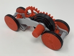
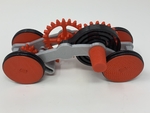
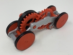
And that's how I designed, printed and assembled Windup Car.
Hope you enjoyed it!
Designer
Greg Zumwalt3d model description
Designing a 3D Printed Windup Car using Autodesk Fusion 360.I've designed, 3D printed, assembled, tested and published quite a few PLA spring mo...tor floating pinion cars and demonstrators over the last few years, so why would I design, print, assemble, test and publish yet another one?
Well, "How I Designed a 3D Printed Windup Car Using Autodesk Fusion 360" includes a four part video series detailing how I designed this 3D printed windup car (with floating pinion drive) using Autodesk Fusion 360. And I've also included the Autodesk Fusion 360 cad file "Windup Floating Pinion Car.f3d" containing the completed design (familiarity with the Autodesk Fusion 360 environment is highly recommended, and if a discrepancy is found between the videos and the cad file, use the cad file).
So if you're interested in my design process for a PLA spring motor powered windup car with floating pinion drive, and / or wish to modify the design to create your own custom version, then this tutorial may indeed be of interest to you.
And if you're simply interested in 3D printing and assembling the car, I've included all STL files required to print the car, along with preparation and assembly instructions.
And finally, what's a floating pinion? In this design a floating pinion is a pinion gear that traverses a guide slot, engaging the PLA spring motor with the drive axle when spring energy is present, and disengaging the PLA spring motor from the drive axle when spring energy is depleted. By disengaging the PLA spring motor from the drive axle, the car is allowed to coast, as opposed to abruptly stopping, when spring energy is depleted providing a significant increase in travel distance.
And as usual, I probably forgot a file or two or who knows what else, so if you have any questions, please do not hesitate to ask as I do make plenty of mistakes.
Designed using Autodesk Fusion 360, sliced using Cura 4.0, and printed in PLA and Tough PLA on an Ultimaker 2+ Extended and an Ultimaker 3 Extended.
The spring motor consists of the "Knob.stl", "Spring.stl", "Pawl.stl" and "Gear, Pawl (24, 2.2).stl". The knob is used to wind the spring, and the pawl and pawl gear provide the ratchet mechanism for winding.
As with all components of this model, I design using what I call "sketch in place" which keeps the sketch in position with the extruded component for easier editing.
The pawl gear, as with all gears used in this model, was designed using a module of 2.2. There are only two gear sizes used in this model; twenty four and eight tooth. For a twenty four tooth gear, the pitch radius is ((24 * 2.2) / 2) or 26.4mm. For an eight tooth gear, the pitch radius is ((8 * 2.2) / 2) or 8.8mm. These dimensions will be used in the next step.
Designing the Gear Train.
Math, math and more math...
The gear train consists of the three gears "Gear, Compound ((24, 2.2), (8, 2.2)).stl", "Gear, Floating Pinion (8, 2.2).stl" and "Gear, Axle (8, 2.2).stl", that transfer the PLA spring motor energy to the drive axle.
As mentioned in the previous step, I used a module value of 2.2 for both the twenty four and eight tooth gears (in practice, when designing a gear train, it is best to use the same module for all gears in the gear train). To determine the spacing between a twenty four and eight tooth gear, the equation I use is:
((24 * 2.2) / 2) + ((8 * 2.2) / 2) + .4mm = 35.6mm.
This simple equation adds the pitch radius of the twenty four tooth gear to the pitch radius of the eight tooth gear, then adds .4mm for slight additional clearance between the gears to account for 3D printing variances (make sure your 3D printer is not over extruding, and don't forget to carefully remove the build plate side "ooze" from the gears using jewelers files or equivalent).
Similarly, the spacing between two eight tooth gears with a module of 2.2 is:
((8 * 2.2) / 2) + ((8 * 2.2) / 2) + .4mm = 18mm.
These two dimensions, 35.6mm and 18mm, are used in this video to space the gears in the gear train.
The total gear ratio from the PLA spring motor to the drive axle is 1:9 (drive to driven), using two gear stages of 1:3 each (e.g. (24 teeth / 8 teeth) = 3, and (3 * 3) = 9). This results in for each rotation of the spring motor, the drive axle will rotate nine times (which is an increase in rotational rate from the PLA spring motor to the drive axle, at the expense of a loss in torque). Thus with a wheel diameter of 47.5mm (as measured using a digital caliper with the O-Rings I used), the distance the car will travel under spring power is approximately (assuming zero traction and friction losses):
(pi * wheel diameter) * 1.25 * 9 = 1678.788574262046mm = 5.5 feet,
where:
1) (pi * wheel diameter) = wheel circumference = 149.2256510455152mm,
2) 1.25 is the number of winds of the PLA spring motor knob, hence the number of times the PLA spring motor will rotate (discounting friction loss and failure to remove the build plate "ooze"),
3) 9 is the total gear ratio from the PLA spring motor to the drive axle (again, drive to driven).
To test the math, I fully wound the PLA spring motor, held the car firmly on a smooth surface along side an extended tape measure, then moved the car forward by hand noting that the floating pinion gear indeed disengaged the PLA spring motor from the drive axle at exactly 5'6" (ok, math isn't that bad after all).
Finally, remember after the PLA spring motor energy is depleted, the floating pinion disengages the PLA spring motor from the drive axle allowing the car to coast. During testing, my cars coasted an additional 15 feet and more after the PLA spring motor energy was depleted.
Designing the Chassis.Whew, glad that math is over...
The chassis consists of the two frames, "Frame, Right.stl" and "Frame, Left.stl".
To gain additional ground clearance, in this video the gear train layout is modified, then the PLA spring motor and gear train components are used to assist with laying out the right frame.
With the right frame complete, the left frame is created by "projecting" the right frame profile, then modifying the various socket and crossmember profiles to allow mating of the two frame sides.
Designing the Axles and Wheels.
There are two unique axles "Axle, Gear, Floating.stl" and "Axle.stl", and one unique "Wheel.stl" designed in this step.
After centering the car assembly, the rear axle is designed and then copied and pasted to create the front axle.
Next the floating pinion axle is designed and positioned
With the axle designs completed, the wheel is designed, then copied and pasted to create the remaining wheels.
3d model print parameters
Purchase, Print and Prepare the Parts.I purchased eight "R-28" O-Rings (38mm ID, 3.5mm Section) for the "tires". These O-Rings fit tight on the w...heels, but slightly larger O-Rings may be used.
As mentioned, I've included all STL files with the components properly oriented for no support 3D printing. If you wish to create your own STL files from the included Autodesk Fusion 360 file "Windup Floating Pinion Car.f3d", remember to properly orient them on the build plate using your slicer prior to printing, and make sure to "hide" (e.g. "light bulb" off) both the O-Ring 1 and O-Ring 2 bodies of the Wheel component prior to creating the STL file for the Wheel component.
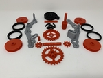
I printed the following quantities and parts at .15mm layer height with the infill percentage and materials as specified:
1) One "Axle, Gear, Floating Pinion (8, 2.2).stl", 50% infill, PLA.
2) Two "Axle.stl", 50% infill, PLA.
3) One "Frame, Left.stl", 100% infill, PLA.
4) One "Frame, Right.stl", 100% infill, PLA.
5) One "Gear, Axle (8, 2.2).stl", 50% infill, PLA.
6) One "Gear, Compound ((24, 2.2), (8, 2.2))", 50% infill, PLA.
7) One "Gear, Floating Pinion (8, 2.2).stl", 50% infill, PLA.
8) One "Gear, Pawl (24, 2.2).stl", 50% infill, PLA.
9) One "Knob.stl", 100% infill, PLA.
10) One "Pawl.stl, 100% infill, Tough PLA (PLA may be used but will provide less torque and longevity).
11) One "Spring.stl", 100% infill, Tough PLA (PLA may be used but will provide less torque and longevity).
12) Four "Wheel.stl", 50% infill, PLA.
Prior to assembly, I test fit and trimmed, filed, sanded, etc. all parts as necessary for smooth movement of moving surfaces, and tight fit for non moving surfaces. If you decide to make your own Windup Car, depending on the colors you chose, your printer model and your printer settings, more or less trimming, filing and/or sanding may be required. I carefully filed all edges that contacted the build plate to make absolutely certain that all build plate "ooze" was removed and that all edges were smooth. I used small jewelers files and plenty of patience to perform this step.
Assembly and Test.
I assembled the car as follows (refer to the photographs for proper location and orientation of the various components):
1) Slid "Knob.stl" into "Frame, Right.stl", making sure the knob rotated freely in the right frame.
2) Pressed "Spring.stl" onto "Knob.stl" while positioning the spring end over the crossmember on the right frame.
3) Pressed "Pawl.stl" onto "Knob.stl". This must be a tight fit for the Knob to remain in place.
4) Placed "Gear, Pawl (24, 2.2).stl" onto "Pawl.stl".
5) Placed "Gear, Compound ((24, 2.2), (8, 2.2)).stl" onto the crossmember on frame, right, making sure the gear rotated freely on the crossmember.
6) Pressed "Axle, Gear, Floating Pinion.stl" into "Gear, Floating Pinion (8, 2.2).stl" making sure the gear was centered on the axle. This must be a tight fit.
7) Placed the floating pinion gear assembly into the guide slot on frame, right, making sure the floating pinion gear assembly rotated and slid freely in the guide slot.
8) Pressed one "Axle.stl" into "Gear, Axle (8, 2.2).stl" such that the gear was 16.5mm from one end of the axle. This is the rear axle assembly and the gear must be a tight fit on the axle.
9) Placed the longer end of the rear axle assembly into the rear axle hole of frame, right making sure the axle assembly rotated freely in the frame.
10) Pressed "Frame, Left.stl" onto the frame, right assembly. This must be a tight fit.
11) Placed the eight O-Rings onto the four "Wheel.stl" (two per wheel). This must be a tight fit to avoid slippage and thus energy loss.
12) Pressed two wheels onto the rear axle assembly such that the outer wheel surfaces were flush with the axle ends. This must be a tight fit, and must rotate freely.
13) Pressed the remaining "Axle.stl" into one of the remaining wheels such that the outer wheel surface was flush with the axle end. This must be a tight fit.
14) Slid this wheel assembly into the front axle hole in the frame assembly, making sure the wheel assembly rotated freely in the frame assembly.
15) Pressed the remaining wheel assembly onto the remaining axle end such that the outer wheel surface was flush with the axle end, and making sure the wheels and axle rotated freely in the frame assembly.
To test the car, hold "Gear, Compound ((24, 2.2), (8, 2.2))" with one hand, wind the spring motor using the Knob with the other hand, set the car on a smooth surface (e.g. gymnasium floor, granite countertop, conference table, etc.) and if all assembly steps were successful, off it goes!
And that's how I designed, printed and assembled Windup Car.
Hope you enjoyed it!