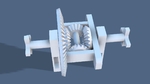
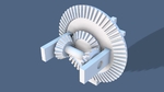
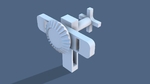
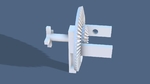
Open differential design 3D for print

6712 Views 3 Likes 0 Downloads Download the piece here from 3dforprint
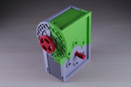
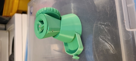
Thanks for checking out my open style gear... differential! I have successfully printed this group of components several times with no issues, so please let me know if you have any problems.
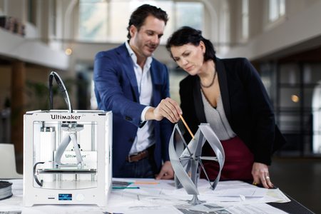
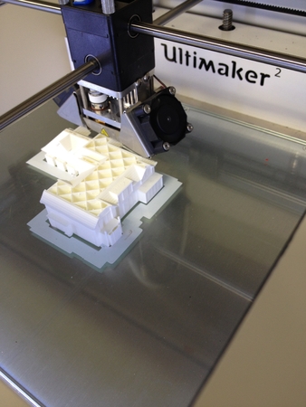
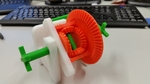
I printed these components at 50mm/s and at a resolution of 100 microns on my Ultimaker 2 with the infill set at 15%. These are just the settings I used however so feel free to experiment if you want faster print times. For the orientation of the parts on the print bed, everything with a notch or long extruded pieces (side captures, ring gear, spider gear support, pinion support base, hand crank) I would recommend printing with the notch or extrusion facing up to minimize support structures. All of the gears should be printed laying flat on the printer bed with the teeth of the gear sticking up.
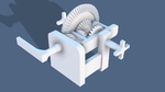
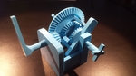
The pictures uploaded after the render will correspond to steps 1-7 of the assembly process. Everything is a press fit and goes together smoothly, so if you find yourself using excessive force at any time assembling, refer back to the pictures, or simply ask for help!
Required components and quantity:
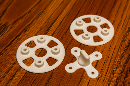
2 Spider Gears
2 Axel Gears
1 Pinion Gear
1 Ring Gear
1 Spider Gear Support
2 Main Axels
1 Spider Gear Axel
1 Ring Gear Side Capture
1 Off-Side Gear Capture
1 Pinion Support Base
1 Hand Crank
While assembling, it is easiest to keep the assembly orientation the same as they are in the pictures. :)
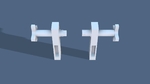
Step 1: Take the 2 main axels and insert them through the 2 side captures. The ring gear side capture has a larger “rider” on it than the off side capture. The notches on both of the captures should be facing towards you.
Step 2: take the assembly on your left (the off side gear capture and axel) and slide the spider support on. Once you have the side capture and spider support on, line up the Hexagonal pattern on one of the axel gears with the axel and press it into place.
Step 3: Take the assembly from your right in step one (ring gear side capture and axel) and slide the ring gear on. Once the ring gear is in place, snap the other axel gear onto the axel.
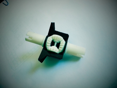
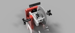
Step 4: On the ring gear side assembly you will notice the two holes on the support structures extruding out of the gear. One of these holes goes clear through the support while the other does not. On the side with the open hole, line up one of the spider gears and twist/slide the shaft through the support structure and spider gear. Once you have one gear on, line up the other on the opposite side and push the shaft through until it is flush with the top of the hole. During this step be careful not to snap the support extrusion off of the ring gear, as it is not hard to do.
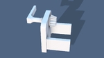
Step 5: Here’s where it starts taking shape! Take the ring gear assembly and the spider support (off side) assembly and attach them together by lining up the notches in the spider support with the tips of the extrusions on the ring gear.
Step 6: Put the gear assembly aside for now…Take the pinion support base and slide the hand crank through it from the flat side to the side with the extrusions. there is a stop collar on the hand crank to bottom it out. Take the pinion gear, line up the hexagonal pattern, and press it onto the hand crank until there is no back and forth play of the assembly in the pinion support base.
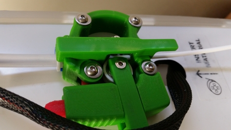
Step 7: This is it! Take the gear assembly and the pinion base assembly and line up the extrusions on the pinion support base with the notches in both of the side captures. Once you press these together, you are done!
To see the differential function, place it on the edge of a table and turn the hand crank while grabbing the handle on either main axel while the other axel magically keeps turning! Enjoy! :)
-Nylon
-ABS...
Designer
Mitch Pricer3d model description
This is a simply design to show how an open differential works and how the basic components are assembled.Thanks for checking out my open style gear... differential! I have successfully printed this group of components several times with no issues, so please let me know if you have any problems.
I printed these components at 50mm/s and at a resolution of 100 microns on my Ultimaker 2 with the infill set at 15%. These are just the settings I used however so feel free to experiment if you want faster print times. For the orientation of the parts on the print bed, everything with a notch or long extruded pieces (side captures, ring gear, spider gear support, pinion support base, hand crank) I would recommend printing with the notch or extrusion facing up to minimize support structures. All of the gears should be printed laying flat on the printer bed with the teeth of the gear sticking up.
The pictures uploaded after the render will correspond to steps 1-7 of the assembly process. Everything is a press fit and goes together smoothly, so if you find yourself using excessive force at any time assembling, refer back to the pictures, or simply ask for help!
Required components and quantity:
2 Spider Gears
2 Axel Gears
1 Pinion Gear
1 Ring Gear
1 Spider Gear Support
2 Main Axels
1 Spider Gear Axel
1 Ring Gear Side Capture
1 Off-Side Gear Capture
1 Pinion Support Base
1 Hand Crank
While assembling, it is easiest to keep the assembly orientation the same as they are in the pictures. :)
Step 1: Take the 2 main axels and insert them through the 2 side captures. The ring gear side capture has a larger “rider” on it than the off side capture. The notches on both of the captures should be facing towards you.
Step 2: take the assembly on your left (the off side gear capture and axel) and slide the spider support on. Once you have the side capture and spider support on, line up the Hexagonal pattern on one of the axel gears with the axel and press it into place.
Step 3: Take the assembly from your right in step one (ring gear side capture and axel) and slide the ring gear on. Once the ring gear is in place, snap the other axel gear onto the axel.
Step 4: On the ring gear side assembly you will notice the two holes on the support structures extruding out of the gear. One of these holes goes clear through the support while the other does not. On the side with the open hole, line up one of the spider gears and twist/slide the shaft through the support structure and spider gear. Once you have one gear on, line up the other on the opposite side and push the shaft through until it is flush with the top of the hole. During this step be careful not to snap the support extrusion off of the ring gear, as it is not hard to do.
Step 5: Here’s where it starts taking shape! Take the ring gear assembly and the spider support (off side) assembly and attach them together by lining up the notches in the spider support with the tips of the extrusions on the ring gear.
Step 6: Put the gear assembly aside for now…Take the pinion support base and slide the hand crank through it from the flat side to the side with the extrusions. there is a stop collar on the hand crank to bottom it out. Take the pinion gear, line up the hexagonal pattern, and press it onto the hand crank until there is no back and forth play of the assembly in the pinion support base.
Step 7: This is it! Take the gear assembly and the pinion base assembly and line up the extrusions on the pinion support base with the notches in both of the side captures. Once you press these together, you are done!
To see the differential function, place it on the edge of a table and turn the hand crank while grabbing the handle on either main axel while the other axel magically keeps turning! Enjoy! :)
3d model print parameters
-PLA-Nylon
-ABS...