Perpetual motion da vinci style iv 3D for print
6961 Views 1 Likes 0 Downloads Download the piece here from 3dforprint
https://youtu.be/sZilHo6HHXk
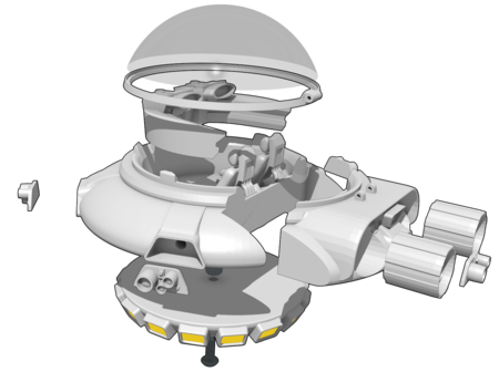
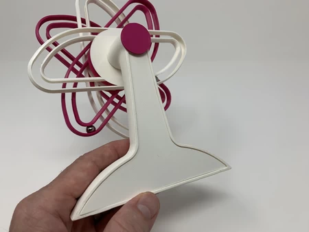
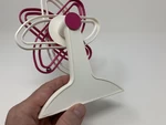
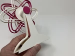
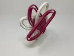
"Perpetual Motion da Vinci Style IV" is the final "perpetual motion machine"... in my series of Mr. da Vinci's "overbalanced wheel" models, the last three designed for a classroom environment. I was asked to create these in order to inspire classroom discussion of Mr. da Vinci's work, and was excited to convert his two dimensional designs into these stylized three dimensional models for the classroom!
As in my previous version "Perpetual Motion Davinci Style III", "perpetual motion" begins when the model is tilted backwards causing a magnet to activate a reed switch which in turn activates a motor that turns the overbalanced wheel via a rubber band transmission. And "perpetual motion" ends when either the battery expires, the rubber band breaks, the motor gives out, or by simply tilting the model forward and tapping on the back near the reed switch to disengage the magnet. In other words, it's still just an illusion.
As usual, I probably forgot a file or two or who knows what else, so if you have any questions, please do not hesitate to ask as I do make plenty of mistakes.
Designed using Autodesk Fusion 360, sliced using Cura 4.0, and printed in PLA on an Ultimaker 2+ Extended and an Ultimaker 3 Extended.
I purchased the following parts:
1) One battery (https://www.adafruit.com/product/258).
2) One JST PH 2-...Pin Cable – Male Header 200mm (https://www.adafruit.com/product/3814).
3) One reed switch (2 by 12mm, Gikfun 20pcs Reed Switch Normally Open N/O Magnetic Induction Switch Electromagnetic for Arduino (Pack of 20pcs) EK1621x2, available on line).
4) One 100 RPM gear motor (100 RPM DC 6V 2.5KG Micro Gear Box Speed Reducing Motor, available online).
5) One rubber band (75mm by 7mm).
6) Four 8mm ball bearings (local hardware store).
7) One 12mm by 3mm neodymium magnet (local hobby shop).
I printed the following parts at .15mm layer height and 20% infill.
1) One "Axle, Wheel.stl".
2) One "Back.stl".
3) One "Base.stl".
4) One "Holder, Reed, Switch.stl".
5) One "Pulley, Motor.stl".
6) One "Pulley, Wheel.stl".
7) One "Track 1.stl".
8) Three "Tracks 2 Through 4.stl".
"Base.stl" must be printed with an inside and outside brim and supports. I've included a Cura 4.0 screen capture of the preview of the base with the brim and supports. The blue material appearing in the screen capture indicates how the brims and supports should appear. The remaining parts do not require brims or supports.
Prior to assembly, I test fit and trimmed, filed, sanded, etc. all parts as necessary for smooth movement of moving surfaces, and tight fit for non moving surfaces. Depending on the colors you chose, your printer model and your printer settings, more or less trimming, filing and/or sanding may be required. I carefully filed all edges that contacted the build plate to make absolutely certain that all build plate "ooze" was removed and that all edges are smooth. I used small jewelers files and plenty of patience to perform this step. The model uses 8mm by 1.25 threaded components, so a tap and die set may be required to clean the threaded parts.
Prepare the Electronics.
To prepare the electronics, I performed the following steps:
1) Soldered the red wire from the JST PH 2-Pin Cable to the motor "+" terminal and the black wire from the JST PH 2-Pin Cable to the motor "-" terminal.
2) At this time, I plugged the battery into the motor connector and made sure the motor shaft was spinning counter clockwise as viewed from the motor shaft end of the motor. If not, I reversed the wires. In either case, I then unplugged the battery.
3) Carefully folded one end of the reed switch as shown.
4) Cut the black wire of the JST PH 2-Pin Cable in the middle then stripped and tinned the cut ends.
5) Soldered one tinned end of the black wire to one end of the reed switch.
6) Soldered the remaining tinned end of the black wire to the remaining end of the reed switch.
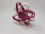
Assemble the Overbalanced Wheel.
To assemble the overbalanced wheel, I performed the following steps.
1) Pressed "Axle, Wheel.stl" into the hexagonal hole in "Track 1.stl".
2) Pressed each of the three "Tracks 2 Through 4.stl" onto the axle in the orientations as shown (each track is positioned -45 degrees from the previous).
3) Positioned one of the 8mm ball bearings onto track 1, then pressed it into the track
4) Repeated this process with the remaining three 8mm ball bearings.
Final Assembly and Operation.
For final assembly of the model, I performed the following steps:
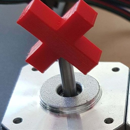
1) Pressed "Pulley, Motor.stl" onto the motor shaft.
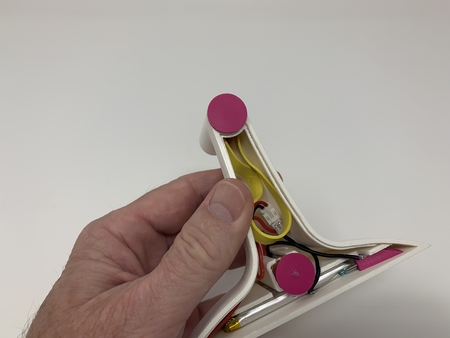
2) Slid the 12mm by 3mm neodymium magnet into the magnet guide slot in "Base.stl".
3) Slid the battery into the battery slot in the base assembly.
4) Connected the battery to the motor plug.
5) Slid the reed switch into the reed switch holder, then pressed the assembly into position in the base assembly.
6) Pressed the motor assembly into the motor slot in the base assembly while carefully orienting the wires to fit in the motor wires slot.
7) Tested the assembly by leaning it backward such that the magnet slid toward the reed switch and activated the motor and noted the motor was spinning clockwise.
8) Stopped the assembly by leaning it forward and tapping on the corner of the base assembly until the magnet slid away from the reed switch.
9) Positioned the rubber band in the assembly.
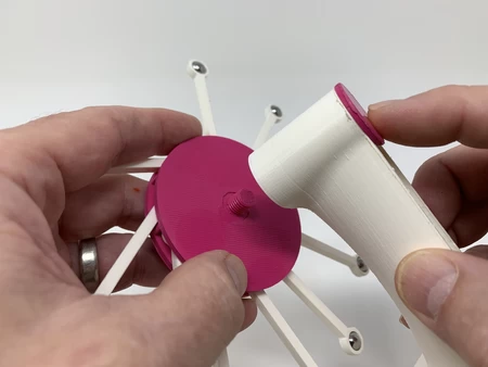
10) For lubrication during insertion, I moistened "Pulley, Wheel.stl" with tap water, then slid it into position such that the rubber band is around the smaller shaft section of the wheel pulley.
11) Threaded the wheel assembly onto the wheel pulley then made sure the wheel assembly rotated easily.
12) Stretched the rubber band around the motor pulley.
13) Made absolutely certain that none of the wiring could come in contact with the moving parts.
14) Pressed "Back.stl" into the base assembly.
To start the model, tilt it backward until the magnet activates the reed switch. To stop the model, tilt it forward and gently tap the back near the reed switch to separate the magnet from the reed switch. With practice, I was able to slightly tilt the model backwards and give the appearance of rotating the wheel counter clockwise to start the model.
And that's how I printed and assembled "Perpetual Motion da Vinci Style IV".
I hope you enjoyed it!
Designer
Greg Zumwalt3d model description
3D Printed Model of Mr. da Vinci's design.https://youtu.be/sZilHo6HHXk
"Perpetual Motion da Vinci Style IV" is the final "perpetual motion machine"... in my series of Mr. da Vinci's "overbalanced wheel" models, the last three designed for a classroom environment. I was asked to create these in order to inspire classroom discussion of Mr. da Vinci's work, and was excited to convert his two dimensional designs into these stylized three dimensional models for the classroom!
As in my previous version "Perpetual Motion Davinci Style III", "perpetual motion" begins when the model is tilted backwards causing a magnet to activate a reed switch which in turn activates a motor that turns the overbalanced wheel via a rubber band transmission. And "perpetual motion" ends when either the battery expires, the rubber band breaks, the motor gives out, or by simply tilting the model forward and tapping on the back near the reed switch to disengage the magnet. In other words, it's still just an illusion.
As usual, I probably forgot a file or two or who knows what else, so if you have any questions, please do not hesitate to ask as I do make plenty of mistakes.
Designed using Autodesk Fusion 360, sliced using Cura 4.0, and printed in PLA on an Ultimaker 2+ Extended and an Ultimaker 3 Extended.
3d model print parameters
Purchase, Print and Prepare the Parts.I purchased the following parts:
1) One battery (https://www.adafruit.com/product/258).
2) One JST PH 2-...Pin Cable – Male Header 200mm (https://www.adafruit.com/product/3814).
3) One reed switch (2 by 12mm, Gikfun 20pcs Reed Switch Normally Open N/O Magnetic Induction Switch Electromagnetic for Arduino (Pack of 20pcs) EK1621x2, available on line).
4) One 100 RPM gear motor (100 RPM DC 6V 2.5KG Micro Gear Box Speed Reducing Motor, available online).
5) One rubber band (75mm by 7mm).
6) Four 8mm ball bearings (local hardware store).
7) One 12mm by 3mm neodymium magnet (local hobby shop).
I printed the following parts at .15mm layer height and 20% infill.
1) One "Axle, Wheel.stl".
2) One "Back.stl".
3) One "Base.stl".
4) One "Holder, Reed, Switch.stl".
5) One "Pulley, Motor.stl".
6) One "Pulley, Wheel.stl".
7) One "Track 1.stl".
8) Three "Tracks 2 Through 4.stl".
"Base.stl" must be printed with an inside and outside brim and supports. I've included a Cura 4.0 screen capture of the preview of the base with the brim and supports. The blue material appearing in the screen capture indicates how the brims and supports should appear. The remaining parts do not require brims or supports.
Prior to assembly, I test fit and trimmed, filed, sanded, etc. all parts as necessary for smooth movement of moving surfaces, and tight fit for non moving surfaces. Depending on the colors you chose, your printer model and your printer settings, more or less trimming, filing and/or sanding may be required. I carefully filed all edges that contacted the build plate to make absolutely certain that all build plate "ooze" was removed and that all edges are smooth. I used small jewelers files and plenty of patience to perform this step. The model uses 8mm by 1.25 threaded components, so a tap and die set may be required to clean the threaded parts.
Prepare the Electronics.
To prepare the electronics, I performed the following steps:
1) Soldered the red wire from the JST PH 2-Pin Cable to the motor "+" terminal and the black wire from the JST PH 2-Pin Cable to the motor "-" terminal.
2) At this time, I plugged the battery into the motor connector and made sure the motor shaft was spinning counter clockwise as viewed from the motor shaft end of the motor. If not, I reversed the wires. In either case, I then unplugged the battery.
3) Carefully folded one end of the reed switch as shown.
4) Cut the black wire of the JST PH 2-Pin Cable in the middle then stripped and tinned the cut ends.
5) Soldered one tinned end of the black wire to one end of the reed switch.
6) Soldered the remaining tinned end of the black wire to the remaining end of the reed switch.
Assemble the Overbalanced Wheel.
To assemble the overbalanced wheel, I performed the following steps.
1) Pressed "Axle, Wheel.stl" into the hexagonal hole in "Track 1.stl".
2) Pressed each of the three "Tracks 2 Through 4.stl" onto the axle in the orientations as shown (each track is positioned -45 degrees from the previous).
3) Positioned one of the 8mm ball bearings onto track 1, then pressed it into the track
4) Repeated this process with the remaining three 8mm ball bearings.
Final Assembly and Operation.
For final assembly of the model, I performed the following steps:
1) Pressed "Pulley, Motor.stl" onto the motor shaft.
2) Slid the 12mm by 3mm neodymium magnet into the magnet guide slot in "Base.stl".
3) Slid the battery into the battery slot in the base assembly.
4) Connected the battery to the motor plug.
5) Slid the reed switch into the reed switch holder, then pressed the assembly into position in the base assembly.
6) Pressed the motor assembly into the motor slot in the base assembly while carefully orienting the wires to fit in the motor wires slot.
7) Tested the assembly by leaning it backward such that the magnet slid toward the reed switch and activated the motor and noted the motor was spinning clockwise.
8) Stopped the assembly by leaning it forward and tapping on the corner of the base assembly until the magnet slid away from the reed switch.
9) Positioned the rubber band in the assembly.
10) For lubrication during insertion, I moistened "Pulley, Wheel.stl" with tap water, then slid it into position such that the rubber band is around the smaller shaft section of the wheel pulley.
11) Threaded the wheel assembly onto the wheel pulley then made sure the wheel assembly rotated easily.
12) Stretched the rubber band around the motor pulley.
13) Made absolutely certain that none of the wiring could come in contact with the moving parts.
14) Pressed "Back.stl" into the base assembly.
To start the model, tilt it backward until the magnet activates the reed switch. To stop the model, tilt it forward and gently tap the back near the reed switch to separate the magnet from the reed switch. With practice, I was able to slightly tilt the model backwards and give the appearance of rotating the wheel counter clockwise to start the model.
And that's how I printed and assembled "Perpetual Motion da Vinci Style IV".
I hope you enjoyed it!