Mac n' cheese 3D for print


885 Views 0 Likes 0 Downloads Download
https://youtu.be/2wOKQ8bfXhI
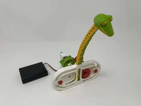
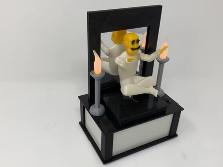
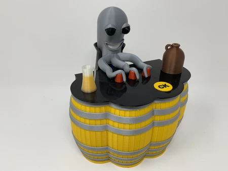
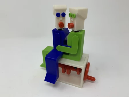
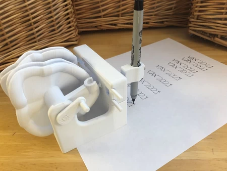
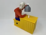
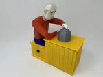
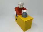
"Mac" is a cheese inspector, and "Cheese" is his nemesis, and a press of the button animat...es Mac's ongoing difficulty with Cheese's appetite.
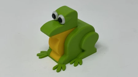
This 3D printed automata is the second in a series of "illusion" themed automata I've been working on. The model was inspired by positivelycreated's "Say Cheese" automaton along with our grandkids "bug eyed squishy frog" bathtub toy.
As usual, I probably forgot a file or two or who knows what else, so if you have any questions, please do not hesitate to ask as I do make plenty of mistakes.
Designed using Autodesk Fusion 360, sliced using Cura 4.4.1, and printed in PLA and breakaway filaments on an Ultimaker 2+ Extended, and Ultimaker 3 Extended and an Ultimaker S5.
I acquired the following parts for this mechanism:
• One N20 6VDC 100RPM gear motor (on line).
• Four 6mm (diameter) by 1.5mm (thick...ness) neodymium magnets (local hobby shop).
• Nine 3mm (diameter) by 1.5mm (thickness) neodymium magnets (local hobby shop).
• 6VDC AAA battery holder (on line).
• Four AAA batteries (my battery stash).
• Two M2 by 16mm screws (local hobby shop).
• Two M2 nuts (local hobby shop).
• One momentary push button switch (Jameco 315651 or equivalent).
• One micro lever switch (CYT1073).
• One machine washer (8mm ID, 12mm OD, 1.5mm thick).
I 3D printed all parts at .15mm layer height with 20% infill. "Eye.3mf" and "Chin.3mf" were printed on a dual extrusion printer using Ultimaker Pearl White PLA, Ultimaker Black PLA and Ultimaker Red PLA. I printed "Cloche.stl" using Ultimaker Metallic Grey for support, "Cheese.stl" using Ultimaker Orange for support and "Gear, Worm.stl" using Ultimaker White Breakaway filament for support. There are two tables to choose from "Table, Closed.stl" and "Table, Open.stl", the majority of this assembly is presented with the open table for viewing the assembly process.
This mechanism is a high precision print and assembly using at times very small precision 3D printed parts in confined spaces. Prior to assembly, test fit and trim, file, drill, sand, etc. all parts as necessary for smooth movement of moving surfaces, and tight fit for non moving surfaces. Depending on you printer, your printer settings and the colors you chose, more or less trimming, filing, drilling and/or sanding may be required. Carefully file all edges that contacted the build plate to make absolutely certain that all build plate "ooze" is removed and that all edges are smooth. I used small jewelers files and plenty of patience to perform this step.
This mechanism also uses threaded assembly, so I used a tap and die set (6mm by 1, 8mm by 1.25) for thread cleaning.
Base Assembly.
To assemble the base, I performed the following steps:
• Attached the micro lever switch to the base using the two M2 screws and nuts.
• Slid "Arm, Arm, Eyes.stl" into the base assembly.
• Threaded "Pin.stl" into the arm.
• Positioned the pin on the arm, arm eyes assembly in the slot in "Pivot, Arm, Eyes.stl" then attached the eye pivot arm to the base assembly using "Axle, Pivot, Arm, Eyes.stl".
• Attached "Arm, Rack.stl" to the base assembly using "Axle, Arm, Rack.stl".
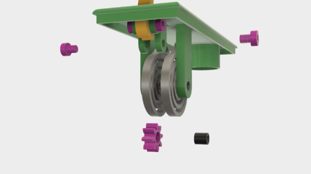
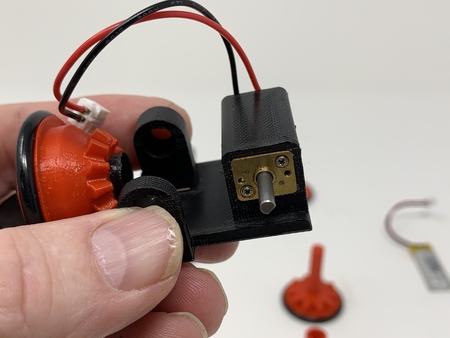
• Attached "Gear, Worm.stl" to the base assembly using "Axle, Gear, Worm.stl" and the washer.
• Pressed the gear motor into the base assembly and worm gear.
• Soldered a 140mm length of 28AWG yellow wire and an 80mm length of 28AWG black wire to one outside pin of the micro lever switch.
• Soldered a 140mm length of 28AWG yellow wire and the black wire from the battery holder to the remaining outside pin of the micro lever switch.
• Soldered the red wire from the battery holder to the gear motor "+" terminal.
• Soldered the black wire from the micro switch to the gear motor "-" terminal.
• Powered the motor to make sure it rotated clockwise when viewed from the motor shaft end of the gear motor (if not, reverse the wires at the motor).
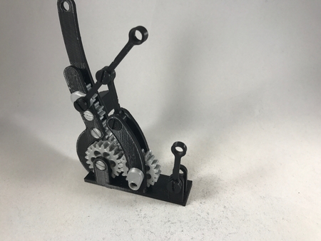
• Pressed "Gear, Worm, Cam.stl", "Cam, Arm, Eyes.stl", "Cam, Holder, Magnets.stl" and "Cam, Arm, Rack.stl" onto "Axle, Main.stl" in the positions and order as shown.
• Pressed three 6mm magnets into "Holder, Magnets.stl" all similarly oriented.
• Positioned the magnet holder assembly over the axle assembly.
• Slid the axle assembly into the base making sure the pin on the head arm was in the slot on the eye cam, then slid the worm gear and rack cams outward to hold the axle assembly in place making sure the axle assembly rotated with ease.
• Adjusted the micro lever switch position such that it just comes in contact with the arm on the eye cam.
• Glued "Mouse.stl" to the table centered over the center hole in the table top.
• Glued small pieces of orange filament to the mouse and table top staying inside the footprint of the cheese.
• Positioned the pin on the magnet holder assembly into the slot in the magnet holder cam.
• Positioned the magnet holder in the slots in the table top, positioned the battery holder between the table legs, slid the table downward to the base assembly, then secured the table to the base using four "Bolt.stl".
Torso Assembly.
To assemble the torso, I performed the following steps:
• Glued "Seat, Top.stl" onto "Seat, Side.stl".
• Secured "Pants.stl" to the seat assembly using three "Bolt.stl".
• Attached "Arm, Left.stl" to "Torso.stl" using "Gear, Arm, Left (1.5m 12t).stl making certain the gear was fully tightened and the arm moved freely.
• Pressed "Hand, Right.stl" into "Arm, Right.stl".
• Attached the right arm assembly to the torso using "Bolt, Arm, Right.stl".
• Positioned "Rack.stl" into the torso assembly such that in engaged with the left arm gear and torso support.
• Pressed the torso assembly onto the seat assembly.
Cloche Assembly.
To assemble the cloche, I performed the following steps:
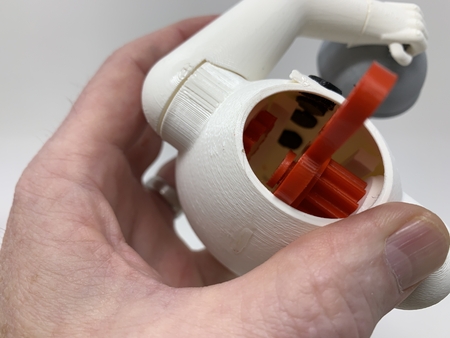
• Pressed one 6mm magnet into the top of the cloche.
• Glued one end of a short piece of 22AWG solid wire to the index hole in the middle finger of "Hand, Left.stl".
• Positioned the cloche assembly under the hand such that the magnet is closer to the finger tips.
• Threaded the wire through the cloche handle then through the hole in the hand wrist.
• Tightened the wire, glued it in place, then trimmed off the excess.
Head Assembly.
To assemble the head, I performed the following steps:
• Pressed one each 3mm magnets into both "Chin.3mf" and "Arm, Eyes, Body.stl" such that the chin attaches to the arm on the right of the chin mount.
• Pressed one each 3mm magnets into both "Eye.3mf".
• Pressed two 3mm magnets into the arm assembly such that the eyes attach to the front side of the arm assembly.
• Removed the chin and eyes and slipped the arm assembly through the mouth and neck.
• Pressed "Arm, Eyes, Coupler.stl" onto the arm assembly.
• Pressed "Axle, Arm, Eyes.stl" through the neck and arm assembly and made certain the mechanism pivoted with ease.
• Pressed the chin assembly into the head assembly and made certain the chin opened and close with ease.
• Positioned both eye assemblies into the eye sockets in the head assembly and made certain the mechanism operated with ease.
• Pressed "Arm, Eyes, Extension.stl" into the arm coupler.
Cheese Assembly.
To assemble the cheese, I performed the following steps:
• Pressed one 3mm magnet in the top of the cheese such that the cheese assembly was attracted to the magnet in the cloche assembly.
• Pressed three 3mm magnets in the bottom of the cheese such that the cheese assembly was attracted to the magnets in the magnet holder assembly.
Final Assembly.
For final assembly, I performed the following steps:
• Slid the head assembly into the torso assembly.
• Attached the assembly to the base assembly using four "Bolt.stl".
• Pressed the left hand (cloche assembly) into the left arm.
• Placed the cheese assembly on the table top.
• Positioned the eye arm slot over the pivot arm pin.
• Threaded the two 140mm wires out the hole in the seat, soldered the wires to the momentary pushbutton switch, then pressed the switch into the hole.
And that is how I 3D printed and assembled "Mac N' Cheese".
I hope you enjoyed it!
Designer
Greg Zumwalt3d model description
An illusion based automaton.https://youtu.be/2wOKQ8bfXhI
"Mac" is a cheese inspector, and "Cheese" is his nemesis, and a press of the button animat...es Mac's ongoing difficulty with Cheese's appetite.
This 3D printed automata is the second in a series of "illusion" themed automata I've been working on. The model was inspired by positivelycreated's "Say Cheese" automaton along with our grandkids "bug eyed squishy frog" bathtub toy.
As usual, I probably forgot a file or two or who knows what else, so if you have any questions, please do not hesitate to ask as I do make plenty of mistakes.
Designed using Autodesk Fusion 360, sliced using Cura 4.4.1, and printed in PLA and breakaway filaments on an Ultimaker 2+ Extended, and Ultimaker 3 Extended and an Ultimaker S5.
3d model print parameters
Parts.I acquired the following parts for this mechanism:
• One N20 6VDC 100RPM gear motor (on line).
• Four 6mm (diameter) by 1.5mm (thick...ness) neodymium magnets (local hobby shop).
• Nine 3mm (diameter) by 1.5mm (thickness) neodymium magnets (local hobby shop).
• 6VDC AAA battery holder (on line).
• Four AAA batteries (my battery stash).
• Two M2 by 16mm screws (local hobby shop).
• Two M2 nuts (local hobby shop).
• One momentary push button switch (Jameco 315651 or equivalent).
• One micro lever switch (CYT1073).
• One machine washer (8mm ID, 12mm OD, 1.5mm thick).
I 3D printed all parts at .15mm layer height with 20% infill. "Eye.3mf" and "Chin.3mf" were printed on a dual extrusion printer using Ultimaker Pearl White PLA, Ultimaker Black PLA and Ultimaker Red PLA. I printed "Cloche.stl" using Ultimaker Metallic Grey for support, "Cheese.stl" using Ultimaker Orange for support and "Gear, Worm.stl" using Ultimaker White Breakaway filament for support. There are two tables to choose from "Table, Closed.stl" and "Table, Open.stl", the majority of this assembly is presented with the open table for viewing the assembly process.
This mechanism is a high precision print and assembly using at times very small precision 3D printed parts in confined spaces. Prior to assembly, test fit and trim, file, drill, sand, etc. all parts as necessary for smooth movement of moving surfaces, and tight fit for non moving surfaces. Depending on you printer, your printer settings and the colors you chose, more or less trimming, filing, drilling and/or sanding may be required. Carefully file all edges that contacted the build plate to make absolutely certain that all build plate "ooze" is removed and that all edges are smooth. I used small jewelers files and plenty of patience to perform this step.
This mechanism also uses threaded assembly, so I used a tap and die set (6mm by 1, 8mm by 1.25) for thread cleaning.
Base Assembly.
To assemble the base, I performed the following steps:
• Attached the micro lever switch to the base using the two M2 screws and nuts.
• Slid "Arm, Arm, Eyes.stl" into the base assembly.
• Threaded "Pin.stl" into the arm.
• Positioned the pin on the arm, arm eyes assembly in the slot in "Pivot, Arm, Eyes.stl" then attached the eye pivot arm to the base assembly using "Axle, Pivot, Arm, Eyes.stl".
• Attached "Arm, Rack.stl" to the base assembly using "Axle, Arm, Rack.stl".
• Attached "Gear, Worm.stl" to the base assembly using "Axle, Gear, Worm.stl" and the washer.
• Pressed the gear motor into the base assembly and worm gear.
• Soldered a 140mm length of 28AWG yellow wire and an 80mm length of 28AWG black wire to one outside pin of the micro lever switch.
• Soldered a 140mm length of 28AWG yellow wire and the black wire from the battery holder to the remaining outside pin of the micro lever switch.
• Soldered the red wire from the battery holder to the gear motor "+" terminal.
• Soldered the black wire from the micro switch to the gear motor "-" terminal.
• Powered the motor to make sure it rotated clockwise when viewed from the motor shaft end of the gear motor (if not, reverse the wires at the motor).
• Pressed "Gear, Worm, Cam.stl", "Cam, Arm, Eyes.stl", "Cam, Holder, Magnets.stl" and "Cam, Arm, Rack.stl" onto "Axle, Main.stl" in the positions and order as shown.
• Pressed three 6mm magnets into "Holder, Magnets.stl" all similarly oriented.
• Positioned the magnet holder assembly over the axle assembly.
• Slid the axle assembly into the base making sure the pin on the head arm was in the slot on the eye cam, then slid the worm gear and rack cams outward to hold the axle assembly in place making sure the axle assembly rotated with ease.
• Adjusted the micro lever switch position such that it just comes in contact with the arm on the eye cam.
• Glued "Mouse.stl" to the table centered over the center hole in the table top.
• Glued small pieces of orange filament to the mouse and table top staying inside the footprint of the cheese.
• Positioned the pin on the magnet holder assembly into the slot in the magnet holder cam.
• Positioned the magnet holder in the slots in the table top, positioned the battery holder between the table legs, slid the table downward to the base assembly, then secured the table to the base using four "Bolt.stl".
Torso Assembly.
To assemble the torso, I performed the following steps:
• Glued "Seat, Top.stl" onto "Seat, Side.stl".
• Secured "Pants.stl" to the seat assembly using three "Bolt.stl".
• Attached "Arm, Left.stl" to "Torso.stl" using "Gear, Arm, Left (1.5m 12t).stl making certain the gear was fully tightened and the arm moved freely.
• Pressed "Hand, Right.stl" into "Arm, Right.stl".
• Attached the right arm assembly to the torso using "Bolt, Arm, Right.stl".
• Positioned "Rack.stl" into the torso assembly such that in engaged with the left arm gear and torso support.
• Pressed the torso assembly onto the seat assembly.
Cloche Assembly.
To assemble the cloche, I performed the following steps:
• Pressed one 6mm magnet into the top of the cloche.
• Glued one end of a short piece of 22AWG solid wire to the index hole in the middle finger of "Hand, Left.stl".
• Positioned the cloche assembly under the hand such that the magnet is closer to the finger tips.
• Threaded the wire through the cloche handle then through the hole in the hand wrist.
• Tightened the wire, glued it in place, then trimmed off the excess.
Head Assembly.
To assemble the head, I performed the following steps:
• Pressed one each 3mm magnets into both "Chin.3mf" and "Arm, Eyes, Body.stl" such that the chin attaches to the arm on the right of the chin mount.
• Pressed one each 3mm magnets into both "Eye.3mf".
• Pressed two 3mm magnets into the arm assembly such that the eyes attach to the front side of the arm assembly.
• Removed the chin and eyes and slipped the arm assembly through the mouth and neck.
• Pressed "Arm, Eyes, Coupler.stl" onto the arm assembly.
• Pressed "Axle, Arm, Eyes.stl" through the neck and arm assembly and made certain the mechanism pivoted with ease.
• Pressed the chin assembly into the head assembly and made certain the chin opened and close with ease.
• Positioned both eye assemblies into the eye sockets in the head assembly and made certain the mechanism operated with ease.
• Pressed "Arm, Eyes, Extension.stl" into the arm coupler.
Cheese Assembly.
To assemble the cheese, I performed the following steps:
• Pressed one 3mm magnet in the top of the cheese such that the cheese assembly was attracted to the magnet in the cloche assembly.
• Pressed three 3mm magnets in the bottom of the cheese such that the cheese assembly was attracted to the magnets in the magnet holder assembly.
Final Assembly.
For final assembly, I performed the following steps:
• Slid the head assembly into the torso assembly.
• Attached the assembly to the base assembly using four "Bolt.stl".
• Pressed the left hand (cloche assembly) into the left arm.
• Placed the cheese assembly on the table top.
• Positioned the eye arm slot over the pivot arm pin.
• Threaded the two 140mm wires out the hole in the seat, soldered the wires to the momentary pushbutton switch, then pressed the switch into the hole.
And that is how I 3D printed and assembled "Mac N' Cheese".
I hope you enjoyed it!