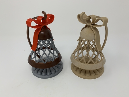
Motorized, articulated t rex(ish) pin walker 3D for print

1488 Views 1 Likes 2 Downloads Download
"It don't mean a thing if it ain't got that swing (Doo wah, doo wah, doo wah, doo wah, doo wah,... doo wah...)" Sorry, an old song (Duke Ellington, 1943) came to mind while designing this model...
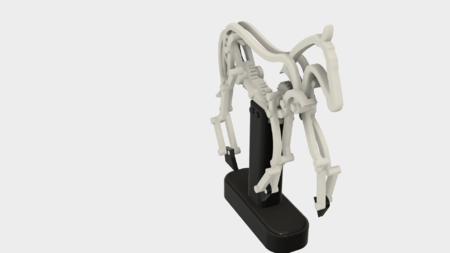
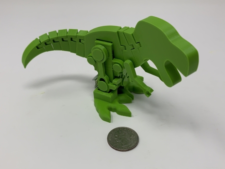
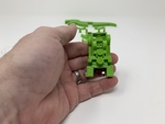
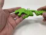
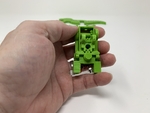
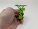
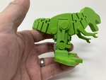
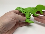
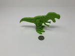
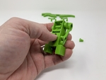
Anyway, "Motorized, Articulated T Rex(ish) Pin Walker" is yet another pin walker design, this time featuring an articulated T Rex styled body that swings from side to side as the model walks along. And while paleontologists around the world will tell you this model does not accurately represent the walking motion of a T Rex, I'm old enough to have actually seen one, and yes it does..., uhh, ok, well no I'm not and no it doesn't, but it was fun designing this model anyway.
The model is designed to swing the articulated T Rex body ("Body.stl") at +- 8 degrees with a rotational a velocity sufficient enough to cause full swing articulation of the 3D printed in place body.
And if you have followed my pin walker designs, you know they were all inspired by the talented works of RobotHut (https://www.youtube.com/user/Robothut) and of rick100 (https://www.youtube.com/channel/UCXe9ERupG5HU4b9KBQ9scqA/featured)
As usual, I probably forgot a file or two or who knows what else, so if you have any questions, please do not hesitate to ask as I do make plenty of mistakes.
Designed using Autodesk Fusion 360, sliced using Cura 4.3.0, and printed in PLA on an Ultimaker 2+ Extended, an Ultimaker 3 Extended, and an Ultimaker S5.
One final note, I receive no compensation in any form for the design, equipment, parts and/or materials used in this model.
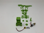
This model uses the following non-3D printed parts:
• One 3.7vdc 100ma Lithium Battery (https://www.adaf...ruit.com/product/1570).
• One JST PH 2-Pin Cable (https://www.adafruit.com/product/3814).
• One N20 6VDC 100RPM gear motor.
• One micro switch (Uxcell a12013100ux0116 High Knob 3P 2 Position 1P2T SPDT Vertical Slide Switch, 0.5 Amp, 50V DC, 50 Piece, 3 mm).
You will also need a suitable battery charger.
I printed one "Base.stl" at .2mm layer height (printing one at .15mm layer height now since the .2mm version appeared awful in the photographs), 20% infill with supports. I printed the following parts at .15mm layer height, 20% infill with no supports:
• One "Arm, Left.stl".
• One "Arm, Right.stl".
• Two "Axle, Leg.stl".
• One "Body.stl" (make sure your 3D printer does not over extrude when printing this part).
• Seven "Bolt.stl".
• One "Cam And Axle.stl".
• One "Cam.stl".
• One "Feet.stl".
• One "Gear, Crown, Axle.stl".
• One "Gear, Crown, Motor.stl".
• Two "Mount, Body.stl".
• Two "Pin.stl".
• One "Seesaw.stl".
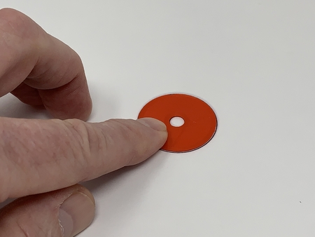
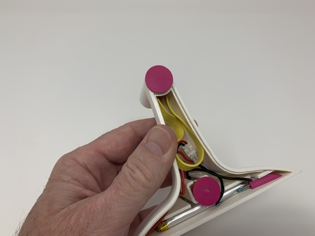
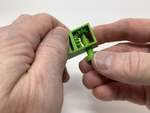
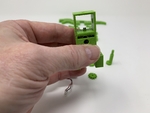
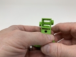
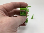
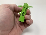
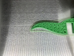
This is a high precision print (see photograph of "Body.stl" at about 1/3 through the 3D printing process) and assembly using at times very small precision 3D printed parts in very tight spaces. Prior to assembly, test fit and trim, file, sand, etc. all parts as necessary for smooth movement of moving surfaces, and tight fit for non moving surfaces. Depending on you printer, your printer settings and the colors you chose, more or less trimming, filing and/or sanding may be required. Carefully file all edges that contacted the build plate to make absolutely certain that all build plate "ooze" is removed and that all edges are smooth. I used small jewelers files and plenty of patience to perform this step.
The model also uses threaded assembly, so I used a tap and die set (6mm by 1) for thread cleaning.
I used light machine oil for lubrication of the gears and axles.
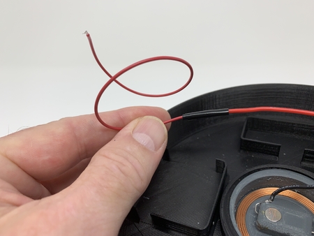
Wire the Motor, Switch and JST Connector.
To wire the the motor, switch and JST connector, I performed the following steps:
• Cut the wires on the JST connector to 40mm in length, then stripped and tinned the ends.
• Soldered the black wire from the JST connector to the motor "-" terminal.
• Soldered the red wire from the JST connector to one of the outside switch terminals.
• Soldered the center switch terminal to the motor "+" terminal such that the switch was centered over the motor.
After wiring, I connected the JST connector to the battery, operated the switch to turn the motor on and off, turned the switch off, then disconnected the battery.
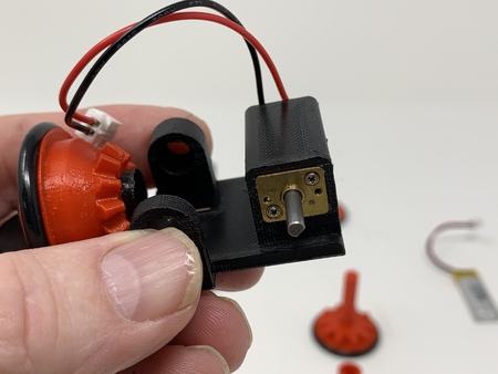
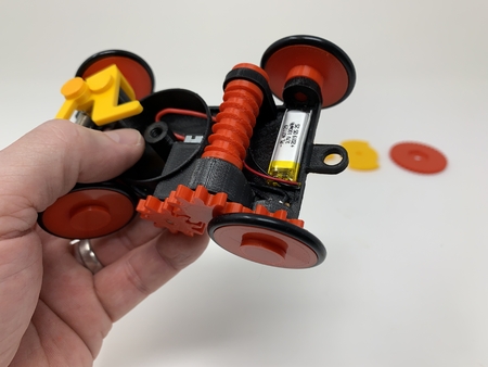
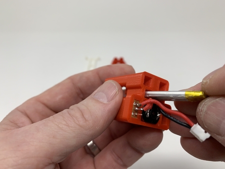
With wiring complete, I pressed the motor into the motor mount on "Base.stl" such that 3mm of the motor shaft extended above the motor gear plate.
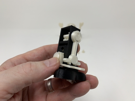
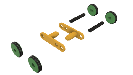
Add the Gears, Cams and Axle.
There are two holes on the top sides of the body assembly, one large, and one small. The larger hole is the model right side which will be useful in assembly the model components in this step and the steps that follow.
To add the gears, cams and axle, I performed the following steps:
• Pressed "Gear, Crown, Motor.stl" onto the motor shaft.
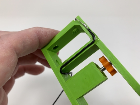
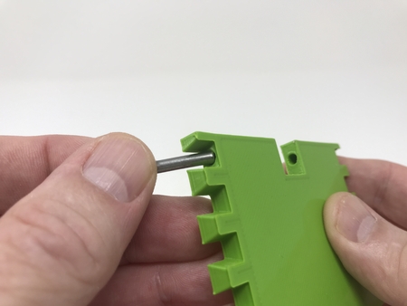
• Slid "Cam And Axle.stl" partially into the large hole at the top right of the base assembly.
• Positioned "Gear, Crown, Axle.stl" centered over the small hole in the base assembly.
• Pressed the cam and axle through the gear and out the small hole at the top left of the base assembly.
• Pressed "Cam.stl" onto the cam and axle 180 degrees out of phase with the cam and axle cam.
At this point, I again connected the JST connector to the battery, turned the switch on, checked for smooth movement of the gears and cams, turned the switch off, then disconnected the battery.
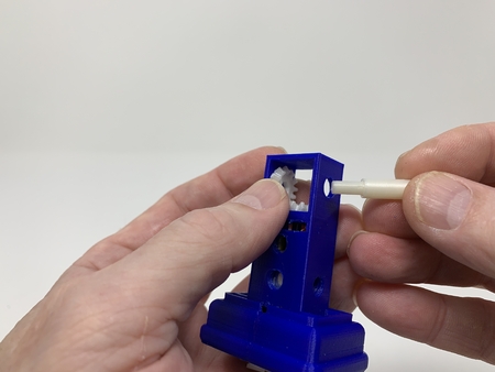
Add the Pins.
To add the pins, I performed the following steps:
• Positioned one "Pin.stl" into the pin slot in the base assembly such that the seesaw • driving pin faced forward.
• Slid the pin ring over the cam.
• Secured the pin in place with one "Axle, Leg.stl".
• I repeated this steps for the remaining pin and leg axle.
At this point, I again connected the JST connector to the battery, turned the switch on, checked for smooth movement of the pins, turned the switch off, then disconnected the battery.
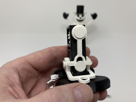
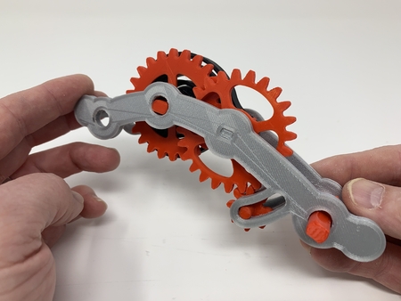
Add the Seesaw and Body Mounts.
To add the seesaw and body mounts, I performed the following steps:
• Manually rotated the motor gear until both seesaw driving pins were level.
• Positioned "Seesaw.stl" onto the front of the base assembly over the lower threaded hole.
• Secured the seesaw using one "Bolt.stl".
• Positioned one "Mount, Body.stl" above the seesaw on the front of the assembly aligned with the upper threaded hole and the seesaw teeth then secured in place using one "Bolt.stl".
• Positioned the remaining "Mount, Body.stl" over the upper threaded hole on the rear of the body assembly then secured in place using one "Bolt.stl".
At this point, I again connected the JST connector to the battery, turned the switch on, checked for smooth movement of the seesaw and front body mount, turned the switch off, then disconnected the battery.
Add the Feet.
To add the feet, I positioned them toes forward over the bottom of the base assembly, then completely pressed into position (watch out for the switch and wiring) until the bottom of the feet were flush with the bottom of the base assembly.
Final Assembly.
For final assembly, I performed the following steps:
• Using double sided tape, I secured the battery to the lower rear of the body assembly.
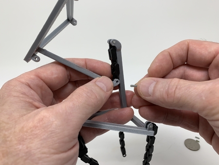
• Pressed "Arm, Right.stl" into the hole on the right side of "Body.stl".
• Pressed "Arm, Left.stl" into the hole on the left side of the body assembly.
• Positioned the body assembly in the two body mounts, head forward.
• Secured the body assembly to the base assembly using four "Bolt.stl".
• Tucked the connectors and excess wiring between the feet.
And that is how I printed and assembled Motorized, Articulated T Rex(ish) Pin Walker.
I hope you enjoyed it!
Designer
Greg Zumwalt3d model description
A motorized articulated T Rex Pin Walker Automata"It don't mean a thing if it ain't got that swing (Doo wah, doo wah, doo wah, doo wah, doo wah,... doo wah...)" Sorry, an old song (Duke Ellington, 1943) came to mind while designing this model...
Anyway, "Motorized, Articulated T Rex(ish) Pin Walker" is yet another pin walker design, this time featuring an articulated T Rex styled body that swings from side to side as the model walks along. And while paleontologists around the world will tell you this model does not accurately represent the walking motion of a T Rex, I'm old enough to have actually seen one, and yes it does..., uhh, ok, well no I'm not and no it doesn't, but it was fun designing this model anyway.
The model is designed to swing the articulated T Rex body ("Body.stl") at +- 8 degrees with a rotational a velocity sufficient enough to cause full swing articulation of the 3D printed in place body.
And if you have followed my pin walker designs, you know they were all inspired by the talented works of RobotHut (https://www.youtube.com/user/Robothut) and of rick100 (https://www.youtube.com/channel/UCXe9ERupG5HU4b9KBQ9scqA/featured)
As usual, I probably forgot a file or two or who knows what else, so if you have any questions, please do not hesitate to ask as I do make plenty of mistakes.
Designed using Autodesk Fusion 360, sliced using Cura 4.3.0, and printed in PLA on an Ultimaker 2+ Extended, an Ultimaker 3 Extended, and an Ultimaker S5.
One final note, I receive no compensation in any form for the design, equipment, parts and/or materials used in this model.
3d model print parameters
Purchase, Print and Prepare the PartsThis model uses the following non-3D printed parts:
• One 3.7vdc 100ma Lithium Battery (https://www.adaf...ruit.com/product/1570).
• One JST PH 2-Pin Cable (https://www.adafruit.com/product/3814).
• One N20 6VDC 100RPM gear motor.
• One micro switch (Uxcell a12013100ux0116 High Knob 3P 2 Position 1P2T SPDT Vertical Slide Switch, 0.5 Amp, 50V DC, 50 Piece, 3 mm).
You will also need a suitable battery charger.
I printed one "Base.stl" at .2mm layer height (printing one at .15mm layer height now since the .2mm version appeared awful in the photographs), 20% infill with supports. I printed the following parts at .15mm layer height, 20% infill with no supports:
• One "Arm, Left.stl".
• One "Arm, Right.stl".
• Two "Axle, Leg.stl".
• One "Body.stl" (make sure your 3D printer does not over extrude when printing this part).
• Seven "Bolt.stl".
• One "Cam And Axle.stl".
• One "Cam.stl".
• One "Feet.stl".
• One "Gear, Crown, Axle.stl".
• One "Gear, Crown, Motor.stl".
• Two "Mount, Body.stl".
• Two "Pin.stl".
• One "Seesaw.stl".
This is a high precision print (see photograph of "Body.stl" at about 1/3 through the 3D printing process) and assembly using at times very small precision 3D printed parts in very tight spaces. Prior to assembly, test fit and trim, file, sand, etc. all parts as necessary for smooth movement of moving surfaces, and tight fit for non moving surfaces. Depending on you printer, your printer settings and the colors you chose, more or less trimming, filing and/or sanding may be required. Carefully file all edges that contacted the build plate to make absolutely certain that all build plate "ooze" is removed and that all edges are smooth. I used small jewelers files and plenty of patience to perform this step.
The model also uses threaded assembly, so I used a tap and die set (6mm by 1) for thread cleaning.
I used light machine oil for lubrication of the gears and axles.
Wire the Motor, Switch and JST Connector.
To wire the the motor, switch and JST connector, I performed the following steps:
• Cut the wires on the JST connector to 40mm in length, then stripped and tinned the ends.
• Soldered the black wire from the JST connector to the motor "-" terminal.
• Soldered the red wire from the JST connector to one of the outside switch terminals.
• Soldered the center switch terminal to the motor "+" terminal such that the switch was centered over the motor.
After wiring, I connected the JST connector to the battery, operated the switch to turn the motor on and off, turned the switch off, then disconnected the battery.
With wiring complete, I pressed the motor into the motor mount on "Base.stl" such that 3mm of the motor shaft extended above the motor gear plate.
Add the Gears, Cams and Axle.
There are two holes on the top sides of the body assembly, one large, and one small. The larger hole is the model right side which will be useful in assembly the model components in this step and the steps that follow.
To add the gears, cams and axle, I performed the following steps:
• Pressed "Gear, Crown, Motor.stl" onto the motor shaft.
• Slid "Cam And Axle.stl" partially into the large hole at the top right of the base assembly.
• Positioned "Gear, Crown, Axle.stl" centered over the small hole in the base assembly.
• Pressed the cam and axle through the gear and out the small hole at the top left of the base assembly.
• Pressed "Cam.stl" onto the cam and axle 180 degrees out of phase with the cam and axle cam.
At this point, I again connected the JST connector to the battery, turned the switch on, checked for smooth movement of the gears and cams, turned the switch off, then disconnected the battery.
Add the Pins.
To add the pins, I performed the following steps:
• Positioned one "Pin.stl" into the pin slot in the base assembly such that the seesaw • driving pin faced forward.
• Slid the pin ring over the cam.
• Secured the pin in place with one "Axle, Leg.stl".
• I repeated this steps for the remaining pin and leg axle.
At this point, I again connected the JST connector to the battery, turned the switch on, checked for smooth movement of the pins, turned the switch off, then disconnected the battery.
Add the Seesaw and Body Mounts.
To add the seesaw and body mounts, I performed the following steps:
• Manually rotated the motor gear until both seesaw driving pins were level.
• Positioned "Seesaw.stl" onto the front of the base assembly over the lower threaded hole.
• Secured the seesaw using one "Bolt.stl".
• Positioned one "Mount, Body.stl" above the seesaw on the front of the assembly aligned with the upper threaded hole and the seesaw teeth then secured in place using one "Bolt.stl".
• Positioned the remaining "Mount, Body.stl" over the upper threaded hole on the rear of the body assembly then secured in place using one "Bolt.stl".
At this point, I again connected the JST connector to the battery, turned the switch on, checked for smooth movement of the seesaw and front body mount, turned the switch off, then disconnected the battery.
Add the Feet.
To add the feet, I positioned them toes forward over the bottom of the base assembly, then completely pressed into position (watch out for the switch and wiring) until the bottom of the feet were flush with the bottom of the base assembly.
Final Assembly.
For final assembly, I performed the following steps:
• Using double sided tape, I secured the battery to the lower rear of the body assembly.
• Pressed "Arm, Right.stl" into the hole on the right side of "Body.stl".
• Pressed "Arm, Left.stl" into the hole on the left side of the body assembly.
• Positioned the body assembly in the two body mounts, head forward.
• Secured the body assembly to the base assembly using four "Bolt.stl".
• Tucked the connectors and excess wiring between the feet.
And that is how I printed and assembled Motorized, Articulated T Rex(ish) Pin Walker.
I hope you enjoyed it!