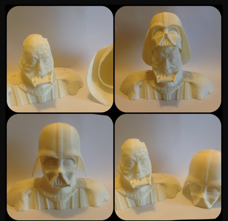
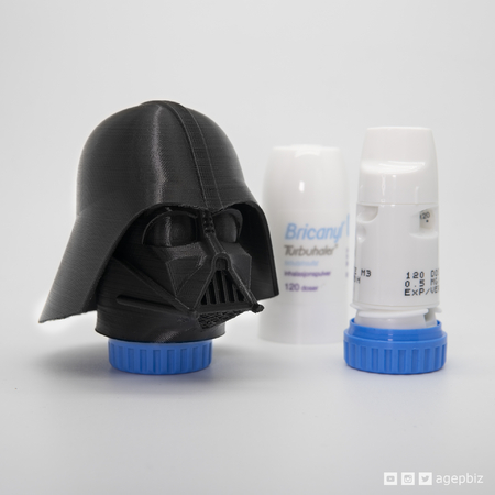
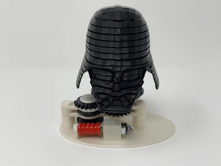
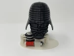
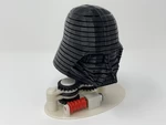
Darth 2: a 3d printed animated darth vader helmet. 3D for print

9932 Views 1 Likes 0 Downloads Download the piece here from 3dforprint
https://youtu.be/8P2rBysBHL8
https://youtu.be/VXNbwr4G26k
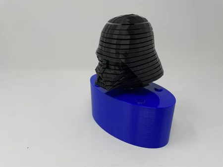
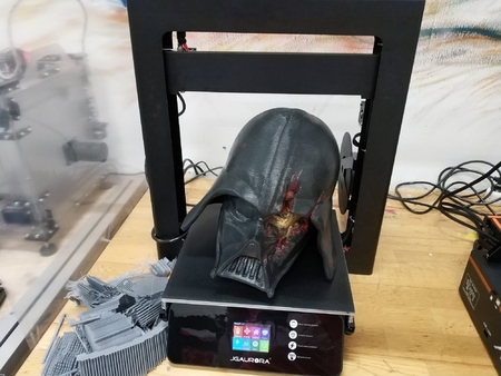
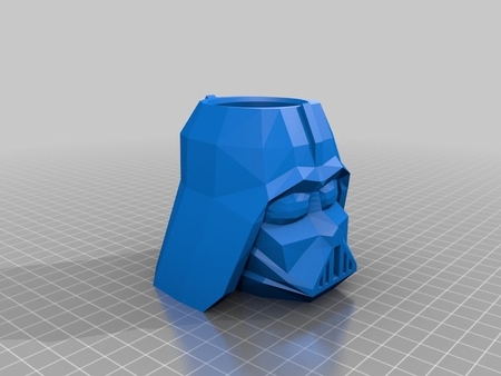
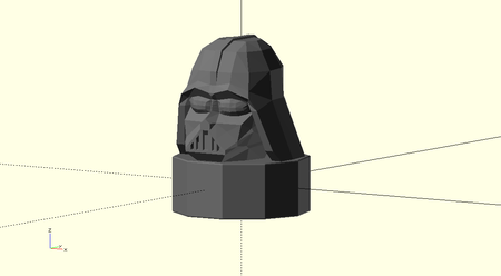
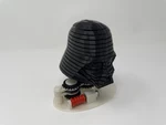
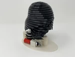
I designed and 3D printed "Darth 2: A 3D P...rinted Animated Darth Vader Helmet", with a twist, for our grandkids who are Star Wars fans!
This animated twisting Darth Vader Helmet is constructed from eighteen helmet slices similar to my "A 3D Printed Animated Valentine Heart for My Valentine!" model. This model animates just the head section from my first Darth design. With extra room in each head slice, I was able to simplify this model by adding 3D printed pins as opposed to the metal pins used in the heart design thus saving the metal pin machining and insertion steps during construction.
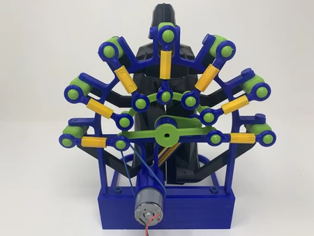
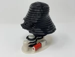
As in the heart design, the motor and gear system in this model is designed to rotate the top slice 180 degrees while holding the bottom slice stationary, then hold the top slice stationary while rotating the bottom slice 180 degrees.
And again as in the heart design, to rotate the inner slices (between the top and bottom) the bottom and inner slices contain 3D printed pins and the inner and top slices contain slots. Each pin fits into the slot in the slice above it, and each slot is designed to allow a 10 degree rotation before contacting the pin below. Thus when the top slice turns 10 degrees, its slot comes in contact with the pin in the slice below and that slice begins to rotate, and when the slice below rotates 10 degrees, the pin in the slice below it begins to rotate. This process continues down the slices until the top rotates 180 degrees at which point the bottom begins to rotate to put the helmet back together.
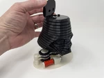
The only contact between each slice must be the pins in the slots, thus careful 3D printing (no warping) and assembly (bearings completely flush with the top and bottom of each slice) are required to successfully 3D print and assemble this model.
As usual I probably forgot a file or two or who knows what else, so if you have any questions, please do not hesitate to comment as I do make plenty of mistakes.
Designed using Autodesk Fusion 360, sliced using Ultimaker Cura 4.8.0, and 3D printed in PLA on Ultimaker S5s.
I acquired the following parts:
• One 2AAA battery back with switch (optional if not using a power supply and jack).
• Two AAA batte...ries (optional if not using a power supply and jack).
• One 300RPM 6VDC N20 gear motor.
• Sixteen bearings (10 x 15 x 4mm).
• 3VDC power supply with compatible coaxial power jack (optional if not using a battery pack and batteries).
I 3D printed all parts at .1mm layer height with 20% infill. I 3D printed 2 "Bolt, Plate.stl", 15 "Spacer.stl" and one each of the remaining parts.
This mechanism is a high precision print and assembly using at times very small precision 3D printed parts in confined spaces with highly precise alignment. I 3D printed all parts using the Ultimaker Cura 4.8.0 "Engineering Profile" on my Ultimaker S5s, which provides a highly accurate tolerance requiring minimal if any trimming, filing, drilling or sanding. However, prior to assembly, I still test fitted and trimmed, filed, drilled, sanded, etc. all parts as necessary for smooth movement of moving surfaces, and tight fit for non moving surfaces. Depending on your slicer, printer, printer settings and the colors you chose, more or less trimming, filing, drilling and/or sanding may be required to successfully recreate this model. I carefully filed all edges that contacted the build plate to make absolutely certain that all build plate "ooze" is removed and that all edges are smooth using small jewelers files and plenty of patience.
This mechanism also uses threaded assembly, so I used a tap and die set (8mm by 1.25) as required for thread cleaning.
Assembling the Darth Vader Helmet Slices.
The bearings and slices are each 4mm thick, and the bearings must be flush with the top and bottom of the slices.
To insert a bearing into a slice, I pressed the bearing partially into the slice then used two small blocks of 3/4" MDF and a bench vice to press the bearing into its final position.
I performed this process for slices 02 ("Slice02.stl") through 17 ("Slice17.stl").
Assembling the Base.
To assemble the base, I performed the following steps:
• Positioned "Gear, Worm.stl" into "Base.stl" as shown with its axle protruding into the axle hole in the base.
• Aligned the gear motor axle with the hole in the worm gear then pressed the gear motor into position as shown.
• Inserted the coaxial power jack into the base and secured it with the included nut.
• Soldered a wire between the coaxial power jack "tip" terminal to the motor "+" terminal (optional, if using a battery pack with switch this step is not necessary).
• Soldered a wire between the coaxial power jack "sleeve" terminal to the motor "-" terminal (optional, if using a battery pack with switch this step is not necessary).
• Placed "Gear, Worm, Wheel.stl" onto the base assembly.
• Placed "Gear Plate Upper.stl" onto the base assembly.
• Pressed "Gear, Bottom, Drive.stl" onto the worm gear wheel hexagonal shaft aligning it as shown.
• Pressed "Axle, Slice18 (top slice).stl" into "Gear, Top, Driven.stl".
• Placed this assembly onto the base assembly aligning it as shown (the axle flats must be on the front and rear).
• Positioned "Gear Plate Upper.stl" on the base assembly.
• Secured the gear plates and gears using two "Bolt, Plate.stl".
• Pressed "Gear, Bottom, Drive.stl" onto the gear drive top hexagonal shaft aligning it as shown.
• Secured the drive gear stack in place with "Axle, Drive.stl".
• Placed "Gear, Bottom, Driven.stl" onto the upper gear plate aligning it as shown.
Assembling the Darth Helmet.
As surprising at it may seem, the bearings I selected for this model are easily distorted by imperfections in the gear stack tower of "Gear Plate Upper.stl" and as such the tower must be filed and sanded smooth in order to remove the 3D printing induced "ooze" imperfections. If this unwanted material is not removed, rotary backlash will be induced in the slices by the distorted bearings (yes, they will indeed distort) resulting in improper operation of the model. So I carefully filed and sanded the upper gear plate tower as needed to reduce this imperfection.
Once satisfied with the gear stack tower, I assembled the Darth helmet as follows:
• Slid "Slice01.stl" down the bearing stack tower then pressed it onto the bottom driven gear in the orientation shown.
• Pressed "Slice02.stl" onto the bearing stack tower down to slice 01 making sure the pin in slice 01 was in the slot of slice 02.
• Pressed one "Spacer.stl" onto the bearing stack tower down to slice 02.
• Repeated the previous two steps for "Slice03.stl" through "Slice16.stl".
• Pressed "Slice17.stl" onto the bearing stack tower down to slice 16 making sure the pin in slice 16 was in the slot of slice 17.
• Pressed "Slice18.stl" onto the slice 18 axle making sure the slot in slice 18 was over the pin in slice 17.
Final Assembly.
For power supply use, I plugged the 3VDC power supply into the coaxial jack, turned on the power supply and made sure the motor rotated clockwise when viewed from the gear motor axle (worm gear) end, and if not, reversed the motor wiring.
For battery use, I placed two AA batteries in the battery pack, turned on the battery pack switch, then soldered the battery pack to the motor such that the motor rotated clockwise when viewed from the gear motor axle (worm gear) end.
And that is how I 3D printed and assembled "Darth 2: A 3D Printed Animated Darth Vader Helmet".
I hope you enjoyed it!
Designer
Greg Zumwalt3d model description
An animated Darth Vader Helmet with a twist.https://youtu.be/8P2rBysBHL8
https://youtu.be/VXNbwr4G26k
I designed and 3D printed "Darth 2: A 3D P...rinted Animated Darth Vader Helmet", with a twist, for our grandkids who are Star Wars fans!
This animated twisting Darth Vader Helmet is constructed from eighteen helmet slices similar to my "A 3D Printed Animated Valentine Heart for My Valentine!" model. This model animates just the head section from my first Darth design. With extra room in each head slice, I was able to simplify this model by adding 3D printed pins as opposed to the metal pins used in the heart design thus saving the metal pin machining and insertion steps during construction.
As in the heart design, the motor and gear system in this model is designed to rotate the top slice 180 degrees while holding the bottom slice stationary, then hold the top slice stationary while rotating the bottom slice 180 degrees.
And again as in the heart design, to rotate the inner slices (between the top and bottom) the bottom and inner slices contain 3D printed pins and the inner and top slices contain slots. Each pin fits into the slot in the slice above it, and each slot is designed to allow a 10 degree rotation before contacting the pin below. Thus when the top slice turns 10 degrees, its slot comes in contact with the pin in the slice below and that slice begins to rotate, and when the slice below rotates 10 degrees, the pin in the slice below it begins to rotate. This process continues down the slices until the top rotates 180 degrees at which point the bottom begins to rotate to put the helmet back together.
The only contact between each slice must be the pins in the slots, thus careful 3D printing (no warping) and assembly (bearings completely flush with the top and bottom of each slice) are required to successfully 3D print and assemble this model.
As usual I probably forgot a file or two or who knows what else, so if you have any questions, please do not hesitate to comment as I do make plenty of mistakes.
Designed using Autodesk Fusion 360, sliced using Ultimaker Cura 4.8.0, and 3D printed in PLA on Ultimaker S5s.
3d model print parameters
Parts.I acquired the following parts:
• One 2AAA battery back with switch (optional if not using a power supply and jack).
• Two AAA batte...ries (optional if not using a power supply and jack).
• One 300RPM 6VDC N20 gear motor.
• Sixteen bearings (10 x 15 x 4mm).
• 3VDC power supply with compatible coaxial power jack (optional if not using a battery pack and batteries).
I 3D printed all parts at .1mm layer height with 20% infill. I 3D printed 2 "Bolt, Plate.stl", 15 "Spacer.stl" and one each of the remaining parts.
This mechanism is a high precision print and assembly using at times very small precision 3D printed parts in confined spaces with highly precise alignment. I 3D printed all parts using the Ultimaker Cura 4.8.0 "Engineering Profile" on my Ultimaker S5s, which provides a highly accurate tolerance requiring minimal if any trimming, filing, drilling or sanding. However, prior to assembly, I still test fitted and trimmed, filed, drilled, sanded, etc. all parts as necessary for smooth movement of moving surfaces, and tight fit for non moving surfaces. Depending on your slicer, printer, printer settings and the colors you chose, more or less trimming, filing, drilling and/or sanding may be required to successfully recreate this model. I carefully filed all edges that contacted the build plate to make absolutely certain that all build plate "ooze" is removed and that all edges are smooth using small jewelers files and plenty of patience.
This mechanism also uses threaded assembly, so I used a tap and die set (8mm by 1.25) as required for thread cleaning.
Assembling the Darth Vader Helmet Slices.
The bearings and slices are each 4mm thick, and the bearings must be flush with the top and bottom of the slices.
To insert a bearing into a slice, I pressed the bearing partially into the slice then used two small blocks of 3/4" MDF and a bench vice to press the bearing into its final position.
I performed this process for slices 02 ("Slice02.stl") through 17 ("Slice17.stl").
Assembling the Base.
To assemble the base, I performed the following steps:
• Positioned "Gear, Worm.stl" into "Base.stl" as shown with its axle protruding into the axle hole in the base.
• Aligned the gear motor axle with the hole in the worm gear then pressed the gear motor into position as shown.
• Inserted the coaxial power jack into the base and secured it with the included nut.
• Soldered a wire between the coaxial power jack "tip" terminal to the motor "+" terminal (optional, if using a battery pack with switch this step is not necessary).
• Soldered a wire between the coaxial power jack "sleeve" terminal to the motor "-" terminal (optional, if using a battery pack with switch this step is not necessary).
• Placed "Gear, Worm, Wheel.stl" onto the base assembly.
• Placed "Gear Plate Upper.stl" onto the base assembly.
• Pressed "Gear, Bottom, Drive.stl" onto the worm gear wheel hexagonal shaft aligning it as shown.
• Pressed "Axle, Slice18 (top slice).stl" into "Gear, Top, Driven.stl".
• Placed this assembly onto the base assembly aligning it as shown (the axle flats must be on the front and rear).
• Positioned "Gear Plate Upper.stl" on the base assembly.
• Secured the gear plates and gears using two "Bolt, Plate.stl".
• Pressed "Gear, Bottom, Drive.stl" onto the gear drive top hexagonal shaft aligning it as shown.
• Secured the drive gear stack in place with "Axle, Drive.stl".
• Placed "Gear, Bottom, Driven.stl" onto the upper gear plate aligning it as shown.
Assembling the Darth Helmet.
As surprising at it may seem, the bearings I selected for this model are easily distorted by imperfections in the gear stack tower of "Gear Plate Upper.stl" and as such the tower must be filed and sanded smooth in order to remove the 3D printing induced "ooze" imperfections. If this unwanted material is not removed, rotary backlash will be induced in the slices by the distorted bearings (yes, they will indeed distort) resulting in improper operation of the model. So I carefully filed and sanded the upper gear plate tower as needed to reduce this imperfection.
Once satisfied with the gear stack tower, I assembled the Darth helmet as follows:
• Slid "Slice01.stl" down the bearing stack tower then pressed it onto the bottom driven gear in the orientation shown.
• Pressed "Slice02.stl" onto the bearing stack tower down to slice 01 making sure the pin in slice 01 was in the slot of slice 02.
• Pressed one "Spacer.stl" onto the bearing stack tower down to slice 02.
• Repeated the previous two steps for "Slice03.stl" through "Slice16.stl".
• Pressed "Slice17.stl" onto the bearing stack tower down to slice 16 making sure the pin in slice 16 was in the slot of slice 17.
• Pressed "Slice18.stl" onto the slice 18 axle making sure the slot in slice 18 was over the pin in slice 17.
Final Assembly.
For power supply use, I plugged the 3VDC power supply into the coaxial jack, turned on the power supply and made sure the motor rotated clockwise when viewed from the gear motor axle (worm gear) end, and if not, reversed the motor wiring.
For battery use, I placed two AA batteries in the battery pack, turned on the battery pack switch, then soldered the battery pack to the motor such that the motor rotated clockwise when viewed from the gear motor axle (worm gear) end.
And that is how I 3D printed and assembled "Darth 2: A 3D Printed Animated Darth Vader Helmet".
I hope you enjoyed it!