3d 打印机和长丝挤出机的长丝传感器 3D打印

8464 视图 1 喜欢 0 下载 下载
它是什么
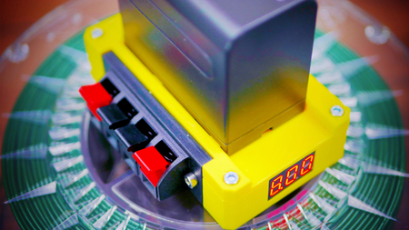
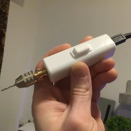
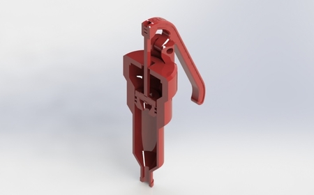
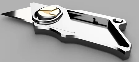
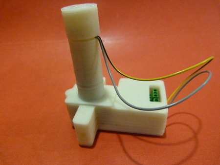
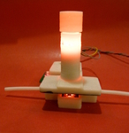
这是一个光学传感器的原型,可在塑料�...�丝进入 3D 打印机或长丝挤出机时实时测量塑料长丝的宽度。它是原型 #3(其他 2 个在 Thingiverse 上)。
它的作用
这个想法是,通过实时宽度测量,3D 打印机(或长丝挤出机)可以补偿挤出流量以适应长丝宽度的变化。此外,如果长丝线轴之间存在差异,则在切片时无需进行校准。g 代码与长丝直径无关。对于长丝挤出机,测量的宽度可用作挤出过程中的反馈。此版本包括定制设计的印刷电路板以及外壳。
对于 3D 打印机
修改了 Marlin 版本以使用传感器数据。
传感器输出以毫米为单位的电压(3v=3mm),电压表上显示该电压。
我对 Marlin 进行了一些更改,以便实时读取细丝直径并补偿挤出速率。代码使用缓冲区来管理传感器测量和喷嘴之间的传输延迟。
Marlin 的主分支现在已初步支持该传感器。但是,它不支持 LCD(尚未提交 - 已提交拉取请求)。您可以在 https://github.com/filipmu/Marlin/tree/Filament-Sensor 找到支持 LCD 的版本
用于细丝挤出机
该原型传感器与最新的 Lyman 挤出机的设计兼容。我与 Hugh 合作构建控制器并将传感器整合到系统中。
http://www.thingiverse.com/thing:380987
其他应用程序
可以独立使用电压表或 LED 面板显示器和 5v 电源(想想 USB 充电器)。无需连接打印机或挤出机即可显示细丝宽度。还可以连接到数据记录器以跟踪灯丝直径。
可以测量此尺寸范围内任何物体的宽度或直径(电线、植物茎等)
传感器规格(我的估计)
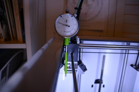
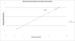
1. 精度:实际用途:3mm 灯丝的比例模式下为 0.02-0.05mm。理论上:传感器的像素宽度为 0.06mm,使用子像素边缘检测,我猜是 5-10 倍,所以是 0.01mm。
2. 采样速度:图像的内部采样为 100Hz,输出平均每秒更新一次。
3. 限制:可能不适用于透明或半透明灯丝。尚未对 1.75mm 灯丝进行全面测试,但应该可以工作。
工作原理:请参阅附件文档。
第一步 - 决定您是否需要用于 3D 打印或灯丝挤出的传感器。
采购
1. 制作 PC 板。
请参阅 Seeedstudio_order_v2.0.zip,了解从 Seeedstudio 订购电路板所需的文件。规格在 PC_board_BOM.pdf 上。
或者,使用 EagleCAD 文件从其他地方订购。PCB 厚度在设计中至关重要,以确保机壳闭合。应为 PC 板 BOM 上列出的 1.6 毫米。
2. 从 BOM(PC 板和 Extruder_version_BOM 或 Printer_version_BOM)订购零件
或者,我这里有少量预焊和测试过的电路板:http://owi.storenvy.com/
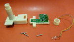
制作机壳零件
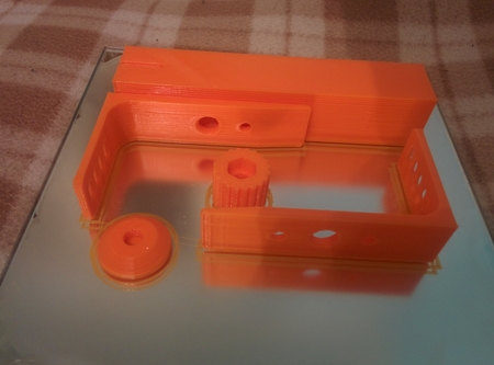
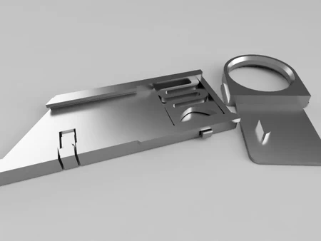
1. 用 ABS 打印出相关零件(打印机或挤出机 .stl),填充率为 20%,喷嘴为 .5 毫米,层高为 .4 毫米。
2. 用平光黑色工艺漆(减少光反射)喷涂塔内和顶板传感器区域。
3. 使用 #9(0.196 英寸)在塔上钻出孔以安装 LED(如果需要) 使用 #50(0.07 英寸)在顶板上钻出螺丝孔,以便 2-56 螺丝可以自攻。
制作电子产品
1. 使用注射器中的焊膏和电煎锅将零件回流焊接到 PC 板上。请参阅 http://www.instructables.com/id/Simple-Skillet-Surface-mount-Soldering/
2. 用仪表检查 PC 板上的焊锡短路并修复。
3. 将两根 4 英寸的电线焊接到将放入传感器塔中的 5 毫米通孔 LED 上。
4. 使用 http://www.evbplus.com/freescale_usbdm_osbdm/usbdm_osbdm_bdm_multilink.html 刷新 MCU。
如果您只想在 MCU 上加载固件,则可以使用编程器板(USBDM 板)附带的软件。如果您安装驱动程序,它会安装一些闪存编程器软件,一个名为 HCS08 编程器。此软件允许您将编译的固件“hex”文件(在压缩项目中名为 FLASH 的目录中称为 FilamentSensorproto2.abs.s19)加载到 MCU 中。在这种情况下不需要 IDE。
如果您想在 IDE 中打开代码,请参阅 freescale 的免费开发工具:freescale.com/webapp/sps/site/overview.jsp?code=CW_SPECIALEDITIONS - 查找微控制器的 eclipse 版本。
最终组装
1. 使用 ABS 汁将塔粘到顶板上,使用所附照片作为指导。塔上的孔应与顶板上的孔对齐。
2. 在喷墨打印机上打印出 Case_labels.pdf,并剪下标签粘贴在外壳背面。用 ABS 汁液粘贴。可以让 ABS 汁液浸入纸张。
3. 将 PC 板压入打印的底板中。确保它完全靠在支架上(使用美工刀清除塑料)
4. 将顶板组件推到底板上(它们应该配对)并用 2-56 螺钉固定(挤出机版本为 3 个,打印机为 4 个)
5. 将 LED 线连接到 +An 和 -Cath 螺钉端子。LED 在 -Cath 端子侧有一个平面。
6. 将 LED 插入塔中(应该轻轻地安装)并拧上 ABS 盖,同时将引线固定到位。
测试和校准
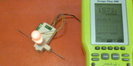
1. 将电压表连接到“Out”端子和“Gnd”端子。
2. 为正确的端子提供 5 伏电源(我使用 USB 充电器和切断的 USB 电缆)
3. LED 应亮起,电压表读数应低于 1v。
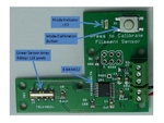
4. 将一根校准杆(精确的 1/16 英寸钻杆)放入传感器中,轻轻保持水平和向下。- 电压应显示 >1 伏。按住传感器上的按钮 >3 秒 - 指示灯 LED 将熄灭,完成后再亮起。
5. 输出电压应显示 1.56 伏,假设电源电压正好是 5.00 伏。可以按下按钮不到 1 秒将模式切换到绝对输出以确认校准。- 有关更多详细信息,请参阅 Board_instructions 文件。
将传感器连接到 3D 打印机或细丝挤出机
有关细丝挤出机的说明,请参阅细丝挤出机:
http://www.thingiverse.com/thing:380987
对于 3D 打印机:
1. 将传感器连接到 3D 打印机控制板上的 A/D 输入和 +5v 电源 - 请参阅 3D
Printer_hookup.pdf 文件。
2. 从 Github https://github.com/filipmu/Marlin/tree/Filament-Sensor 下载修改后的 Marlin 版本 - 希望将来某个时候将其纳入官方 Marlin。
3. 根据打印机的需要更改配置文件。此代码中有一些新的细丝传感器定义。
4. 将固件上传到您的 3D
打印机。
将传感器与您的挤出机或打印机配合使用
有关长丝挤出机的说明,请参阅长丝挤出机:
http://www.thingiverse.com/thing:380987
对于 3D 打印机:
1. 将自定义 g 代码添加到您的切片机软件以启用传感器:
M405;打开长丝控制
2. 当打印机空闲时,您可以通过键入并向打印机发送 M407 来查看长丝传感器读数。它会将直径返回到日志。
此原型版本(#3)中的新增内容
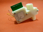
我改进了 PC 板(现在是版本 2),以使用螺丝端子进行连接。我删除了未使用的组件。电路板的尺寸与原型 #2 的先前 V1 相同。请注意,原型 #1 有电路板 V0(手工制作),因此电路板版本号比原型号晚一个。
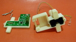
有两种外壳设计,一种用于 3D 打印机,一种用于长丝挤出机。相同的 PC 板适用于这两种设备。
先前版本的信息
先前版本网站上有很多相关讨论:
版本 2:http://www.thingiverse.com/thing:89044
版本 1:http://www.thingiverse.com/thing:70775
获取零件(供应商来源)
1. PC 板 - 文件包括您需要提交给 Seeedstudio 的电路板服务的所有内容:http://www.seeedstudio.com/service/index.php?r=pcb
2. 电子元件可从 Mouser 订购。 Digikey 也是另一种选择。
3. Enco 提供校准钻杆:http://www.use-enco.com/CGI/INSRIT?PMAKA=408-0001&PMPXNO=939654&PARTPG=INLMK32
4. 如果您想避免制作和焊接自己的电路板,我出售有限数量的完整且经过测试的印刷电路板套件:http://owi.storenvy.com/
从这里获取它:
以下是一些关于如何获取这个想法的想法,其中一些是其他人提出的:
1. 它只能测量 1 维的直径。灯丝可能是椭圆形的,因此要测量更多维度。一些选项是多个图像传感器,或使用 RC 伺服器物理扫描灯丝周围的传感器并进行几何平均。
2. 提高现有精度 - 使用镜头或更好的照明以确保灯丝与传感器的距离不会影响读数。也可以使用小滚轮将灯丝固定到位。
3. 改进输出,使其产生数字 I2C 输出而不是模拟电压。
4. 更新 Marlin,使传感器也检查灯丝末端。
5. 传感器应该适用于 1.75 毫米灯丝,但需要更多信息/反馈/工作来改进设计(我没有使用 1.75 毫米灯丝的打印机)
6. 校准杆在欧洲很难找到,因此让电路板也与 3 毫米校准杆配合使用。
7. 制作一个带有 Atmel 处理器的版本,以便它可以使用 Arduino 工具链。
8. 使用现有的 Arduino 板和传感器板:
- ABS 灯丝
- 黑色丙烯酸工艺漆
- 传感器 PC 板(请参阅附件规格)
- 传感器板的电子...元件(请参阅附件规格)
- 电子耗材(焊料、SMD 焊膏、连接线等)
- Freescale HCS08 编程器(请参阅详情)
- 修改后的 Marlin 软件(请参阅详情)
- 校准杆(.0630mm 钻杆)
设计师
filipmulier3D 模型描述
原型传感器可以实时测量 3D 打印机或长丝挤出机的长丝直径。它是什么
这是一个光学传感器的原型,可在塑料�...�丝进入 3D 打印机或长丝挤出机时实时测量塑料长丝的宽度。它是原型 #3(其他 2 个在 Thingiverse 上)。
它的作用
这个想法是,通过实时宽度测量,3D 打印机(或长丝挤出机)可以补偿挤出流量以适应长丝宽度的变化。此外,如果长丝线轴之间存在差异,则在切片时无需进行校准。g 代码与长丝直径无关。对于长丝挤出机,测量的宽度可用作挤出过程中的反馈。此版本包括定制设计的印刷电路板以及外壳。
对于 3D 打印机
修改了 Marlin 版本以使用传感器数据。
传感器输出以毫米为单位的电压(3v=3mm),电压表上显示该电压。
我对 Marlin 进行了一些更改,以便实时读取细丝直径并补偿挤出速率。代码使用缓冲区来管理传感器测量和喷嘴之间的传输延迟。
Marlin 的主分支现在已初步支持该传感器。但是,它不支持 LCD(尚未提交 - 已提交拉取请求)。您可以在 https://github.com/filipmu/Marlin/tree/Filament-Sensor 找到支持 LCD 的版本
用于细丝挤出机
该原型传感器与最新的 Lyman 挤出机的设计兼容。我与 Hugh 合作构建控制器并将传感器整合到系统中。
http://www.thingiverse.com/thing:380987
其他应用程序
可以独立使用电压表或 LED 面板显示器和 5v 电源(想想 USB 充电器)。无需连接打印机或挤出机即可显示细丝宽度。还可以连接到数据记录器以跟踪灯丝直径。
可以测量此尺寸范围内任何物体的宽度或直径(电线、植物茎等)
传感器规格(我的估计)
1. 精度:实际用途:3mm 灯丝的比例模式下为 0.02-0.05mm。理论上:传感器的像素宽度为 0.06mm,使用子像素边缘检测,我猜是 5-10 倍,所以是 0.01mm。
2. 采样速度:图像的内部采样为 100Hz,输出平均每秒更新一次。
3. 限制:可能不适用于透明或半透明灯丝。尚未对 1.75mm 灯丝进行全面测试,但应该可以工作。
工作原理:请参阅附件文档。
第一步 - 决定您是否需要用于 3D 打印或灯丝挤出的传感器。
采购
1. 制作 PC 板。
请参阅 Seeedstudio_order_v2.0.zip,了解从 Seeedstudio 订购电路板所需的文件。规格在 PC_board_BOM.pdf 上。
或者,使用 EagleCAD 文件从其他地方订购。PCB 厚度在设计中至关重要,以确保机壳闭合。应为 PC 板 BOM 上列出的 1.6 毫米。
2. 从 BOM(PC 板和 Extruder_version_BOM 或 Printer_version_BOM)订购零件
或者,我这里有少量预焊和测试过的电路板:http://owi.storenvy.com/
制作机壳零件
1. 用 ABS 打印出相关零件(打印机或挤出机 .stl),填充率为 20%,喷嘴为 .5 毫米,层高为 .4 毫米。
2. 用平光黑色工艺漆(减少光反射)喷涂塔内和顶板传感器区域。
3. 使用 #9(0.196 英寸)在塔上钻出孔以安装 LED(如果需要) 使用 #50(0.07 英寸)在顶板上钻出螺丝孔,以便 2-56 螺丝可以自攻。
制作电子产品
1. 使用注射器中的焊膏和电煎锅将零件回流焊接到 PC 板上。请参阅 http://www.instructables.com/id/Simple-Skillet-Surface-mount-Soldering/
2. 用仪表检查 PC 板上的焊锡短路并修复。
3. 将两根 4 英寸的电线焊接到将放入传感器塔中的 5 毫米通孔 LED 上。
4. 使用 http://www.evbplus.com/freescale_usbdm_osbdm/usbdm_osbdm_bdm_multilink.html 刷新 MCU。
如果您只想在 MCU 上加载固件,则可以使用编程器板(USBDM 板)附带的软件。如果您安装驱动程序,它会安装一些闪存编程器软件,一个名为 HCS08 编程器。此软件允许您将编译的固件“hex”文件(在压缩项目中名为 FLASH 的目录中称为 FilamentSensorproto2.abs.s19)加载到 MCU 中。在这种情况下不需要 IDE。
如果您想在 IDE 中打开代码,请参阅 freescale 的免费开发工具:freescale.com/webapp/sps/site/overview.jsp?code=CW_SPECIALEDITIONS - 查找微控制器的 eclipse 版本。
最终组装
1. 使用 ABS 汁将塔粘到顶板上,使用所附照片作为指导。塔上的孔应与顶板上的孔对齐。
2. 在喷墨打印机上打印出 Case_labels.pdf,并剪下标签粘贴在外壳背面。用 ABS 汁液粘贴。可以让 ABS 汁液浸入纸张。
3. 将 PC 板压入打印的底板中。确保它完全靠在支架上(使用美工刀清除塑料)
4. 将顶板组件推到底板上(它们应该配对)并用 2-56 螺钉固定(挤出机版本为 3 个,打印机为 4 个)
5. 将 LED 线连接到 +An 和 -Cath 螺钉端子。LED 在 -Cath 端子侧有一个平面。
6. 将 LED 插入塔中(应该轻轻地安装)并拧上 ABS 盖,同时将引线固定到位。
测试和校准
1. 将电压表连接到“Out”端子和“Gnd”端子。
2. 为正确的端子提供 5 伏电源(我使用 USB 充电器和切断的 USB 电缆)
3. LED 应亮起,电压表读数应低于 1v。
4. 将一根校准杆(精确的 1/16 英寸钻杆)放入传感器中,轻轻保持水平和向下。- 电压应显示 >1 伏。按住传感器上的按钮 >3 秒 - 指示灯 LED 将熄灭,完成后再亮起。
5. 输出电压应显示 1.56 伏,假设电源电压正好是 5.00 伏。可以按下按钮不到 1 秒将模式切换到绝对输出以确认校准。- 有关更多详细信息,请参阅 Board_instructions 文件。
将传感器连接到 3D 打印机或细丝挤出机
有关细丝挤出机的说明,请参阅细丝挤出机:
http://www.thingiverse.com/thing:380987
对于 3D 打印机:
1. 将传感器连接到 3D 打印机控制板上的 A/D 输入和 +5v 电源 - 请参阅 3D
Printer_hookup.pdf 文件。
2. 从 Github https://github.com/filipmu/Marlin/tree/Filament-Sensor 下载修改后的 Marlin 版本 - 希望将来某个时候将其纳入官方 Marlin。
3. 根据打印机的需要更改配置文件。此代码中有一些新的细丝传感器定义。
4. 将固件上传到您的 3D
打印机。
将传感器与您的挤出机或打印机配合使用
有关长丝挤出机的说明,请参阅长丝挤出机:
http://www.thingiverse.com/thing:380987
对于 3D 打印机:
1. 将自定义 g 代码添加到您的切片机软件以启用传感器:
M405;打开长丝控制
2. 当打印机空闲时,您可以通过键入并向打印机发送 M407 来查看长丝传感器读数。它会将直径返回到日志。
此原型版本(#3)中的新增内容
我改进了 PC 板(现在是版本 2),以使用螺丝端子进行连接。我删除了未使用的组件。电路板的尺寸与原型 #2 的先前 V1 相同。请注意,原型 #1 有电路板 V0(手工制作),因此电路板版本号比原型号晚一个。
有两种外壳设计,一种用于 3D 打印机,一种用于长丝挤出机。相同的 PC 板适用于这两种设备。
先前版本的信息
先前版本网站上有很多相关讨论:
版本 2:http://www.thingiverse.com/thing:89044
版本 1:http://www.thingiverse.com/thing:70775
获取零件(供应商来源)
1. PC 板 - 文件包括您需要提交给 Seeedstudio 的电路板服务的所有内容:http://www.seeedstudio.com/service/index.php?r=pcb
2. 电子元件可从 Mouser 订购。 Digikey 也是另一种选择。
3. Enco 提供校准钻杆:http://www.use-enco.com/CGI/INSRIT?PMAKA=408-0001&PMPXNO=939654&PARTPG=INLMK32
4. 如果您想避免制作和焊接自己的电路板,我出售有限数量的完整且经过测试的印刷电路板套件:http://owi.storenvy.com/
从这里获取它:
以下是一些关于如何获取这个想法的想法,其中一些是其他人提出的:
1. 它只能测量 1 维的直径。灯丝可能是椭圆形的,因此要测量更多维度。一些选项是多个图像传感器,或使用 RC 伺服器物理扫描灯丝周围的传感器并进行几何平均。
2. 提高现有精度 - 使用镜头或更好的照明以确保灯丝与传感器的距离不会影响读数。也可以使用小滚轮将灯丝固定到位。
3. 改进输出,使其产生数字 I2C 输出而不是模拟电压。
4. 更新 Marlin,使传感器也检查灯丝末端。
5. 传感器应该适用于 1.75 毫米灯丝,但需要更多信息/反馈/工作来改进设计(我没有使用 1.75 毫米灯丝的打印机)
6. 校准杆在欧洲很难找到,因此让电路板也与 3 毫米校准杆配合使用。
7. 制作一个带有 Atmel 处理器的版本,以便它可以使用 Arduino 工具链。
8. 使用现有的 Arduino 板和传感器板:
3D模型打印参数
摘要列表(详情请参阅附件)- ABS 灯丝
- 黑色丙烯酸工艺漆
- 传感器 PC 板(请参阅附件规格)
- 传感器板的电子...元件(请参阅附件规格)
- 电子耗材(焊料、SMD 焊膏、连接线等)
- Freescale HCS08 编程器(请参阅详情)
- 修改后的 Marlin 软件(请参阅详情)
- 校准杆(.0630mm 钻杆)