Inductive candle 3D for print


22721 Views 1 Likes 0 Downloads Download the piece here from 3dforprint
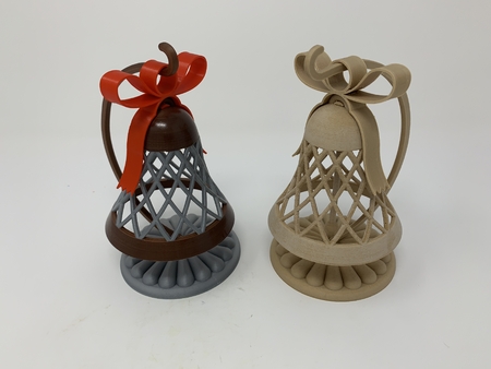
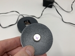
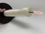
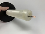
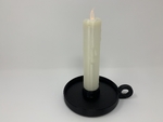
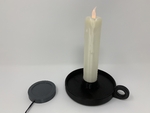
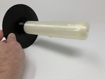
"Inductive Candle" is an inductively charged (similar to smart phone or watch "cable free" chargers) ca...ndle that automatically "lights" when removed from the charging base and "extinguishes" when returned to the charging base.
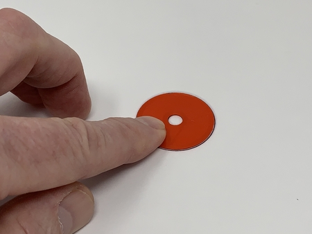
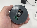
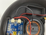
The base assembly contains an inductive transmitter and coil and a 12mm diameter by 3mm thick neodymium magnet.
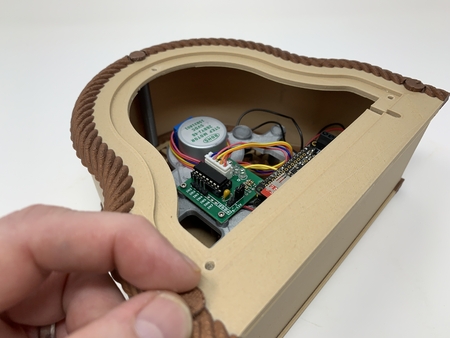
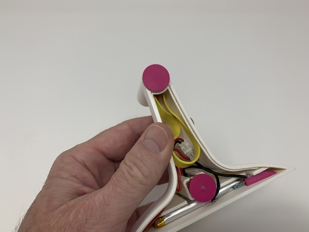
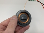
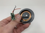
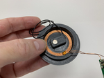
The candle assembly contains an inductive coil and receiver, a lithium polymer battery charger, a lithium polymer battery, a 6mm diameter by 2mm thick neodymium magnet, a normally open reed switch, and a flickering LED.
When the candle assembly is removed from the base assembly, the neodymium magnet in the candle assembly activates the reed switch which illuminates the LED using the LiPo battery as the power source. When the candle assembly is returned to the base assembly, the neodymium magnet in the base assembly alters the magnetic field of the neodymium magnet in the candle assembly deactivating the reed switch and extinguishing the LED while the inductive charging system charges the LiPo battery. Since the charging system utilizes air coil induction which is not as efficient as cable charging, the design extinguishes the candle when the candle assembly is returned to the base assembly for charging.
I purchased the inductive charging system from Adafruit.com (I really like that place) who indicates the system will operate from 9 to 12vdc. When operated at 12vdc however, the inductive charging system generates heat that may be excessive for most PLA filaments. Using an IR thermometer I measured the temperature on "Base, Cover.stl" at 56° C (approximately 133° F) when using a 12vdc power source. Thus if you decide to use a 12vdc power source I recommend printing "Base, Cover.stl", "Base.stl" and "Lamp, Base Interface.stl" using Ultimaker CPE+ or equivalent filament having a higher temperature rating than PLA.
And as usual, I probably forgot a file or two or who knows what else, so if you have any questions, please do not hesitate to ask as I do make plenty of mistakes.
Designed using Autodesk Fusion 360 and Meshmixer 3.5.474, sliced using Cura 4.1 and printed in Ultimaker PLA and CPE+ filament on an Ultimaker 2+ Extended and an Ultimaker 3 Extended.
One final note, I receive no compensation in any form whatsoever for the use of any of the components and/or materials used in this design.
I purchased (or salvaged) the following parts:
1) One Inductive Charger Set (https://www.adafruit.com/pro...duct/1407).
2) One USB LiIon/LiPoly charger (https://www.adafruit.com/product/259).
3) One LiPo Battery (https://www.adafruit.com/product/258).
4) One reed switch (2 by 12mm, Gikfun 20pcs Reed Switch Normally Open N/O Magnetic Induction Switch Electromagnetic for Arduino (Pack of 20pcs) EK1621x2, available on line).
5) One neodymium magnet (12mm diameter by 3mm thick, local hobby shop).
6) One neodymium magnet (6mm diameter by 2mm thick, local hobby shop).
7) One salvaged 9 - 12vdc 500ma power supply (note using a 12vdc power supply will decrease charging time at the expense of increased heat, while alternatively using a 9vdc power supply will increase charging time but with reduced heat).
8) One salvaged tea lamp LED (https://www.amazon.com/gp/product/B00T28FWVS/ref=ppx_yo_dt_b_asin_image_o00_s00?ie=UTF8&psc=1).
9) One salvaged 100 ohm resistor.
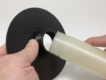
10) One white drinking straw ("borrowed" from a local restaurant) cut to 180mm in length This piece is optional in order to disguise the wiring in the candle if the candle is printed with translucent / transparent material.
Parts I Printed:
I printed one each of all parts at .15mm layer height, 20% infill. Since the inductive charging system generates heat, I printed "Base, Cover.stl", "Base.stl" and "Lamp, Base Interface.stl" using Ultimaker CPE+ filament. The remaining parts were printed in Ultimaker PLA filament.
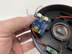
Assemble the Charging Base.
To assemble the Charging Base, I performed the following steps:
1) Carefully placed the two magnet faces together, then marked an "X" on the outside faces with an indelible ink pen.
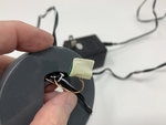
2) Desoldered and removed the red and black wires from the inductive charger transmitter board.
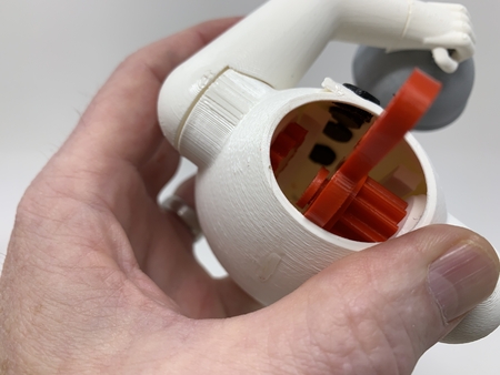
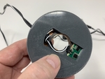
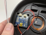
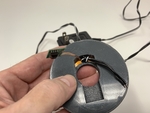
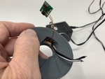
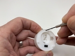
3) Slid the inductive charger transmitter board down through the slot in "Base.stl".
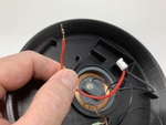
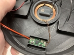
4) Pressed the inductive charger coil into the ring in the top of the base, aligning the wires from the coil to the inductive charger transmitter board with the slot.
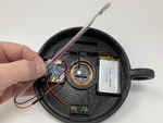
5) Slid the power supply wires into the hole in the side of the base.
6) Tied a knot in the power supply wires for strain relief.
7) Applied double sided tape to the bottom of the inductive charger transmitter board.
8) Pressed the inductive charger transmitter board into the base.
9) Soldered the positive ("+") power supply wire to the inductive charger transmitter board "+" pin.
10) Soldered the negative ("-") power supply wire to the inductive charger transmitter board "-" pin.
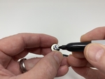
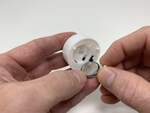
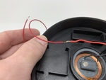
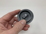
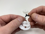
11) Pressed the 12mm diameter by 3mm thick neodymium magnet into "Base, Cover.stl" such that the "X" mark is visible.
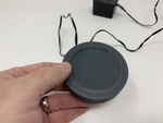
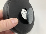
12) Pressed the base cover in place on top of the base.
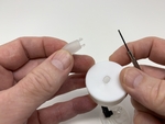
Disassemble the Tea Lamp.
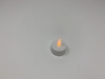
The design uses the flickering LED and the flame lens from the tea lamp I salvaged. To obtain these parts, disassembly of the tea lamp is required. To disassemble the tea lamp, I performed the following steps:
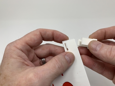
1) Removed the battery cover and battery from the tea lamp.
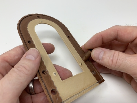
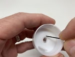
2) Used a small screwdriver to remove the cover from tea lamp.
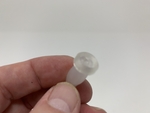
3) Used a small screwdriver to remove the lens from the tea lamp cover.
4) Removed the LED and switch from the tea lamp base.
5) Removed the switch from the LED.
Assemble the Candle Electronics.
To assemble the candle electronics, I performed the following steps:
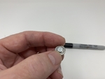
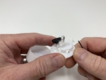
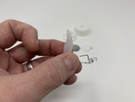
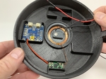
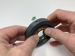
1) Pressed the 6mm diameter by 2mm thick neodymium magnet into the hole in "Lamp, Candle, Interface.stl" such that the "X" mark (the mark made in step 2) is visible.
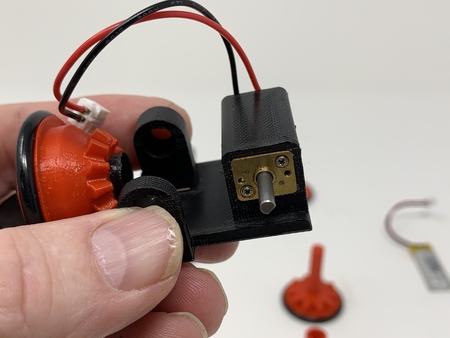
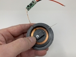
2) Pressed the inductive charger receiver coil into this assembly.
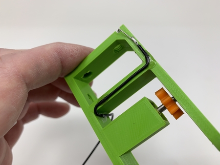
3) Slid the reed switch into the this assembly.
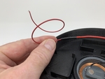
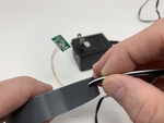
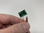
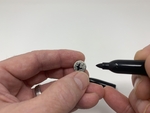
4) Using locking forceps on each lead (NOT THE GLASS), I carefully centered the read switch then bent the reed switch leads as shown. If you do not use locking forceps or an equivalent method, you may break the reed switch glass and permanently damaging the reed switch.
5) Soldered a 300mm length of black 26 AWG wire to one contact of the read switch.
6) Soldered the black wire on the JST connector that came with the USB LiIon/LiPoly charger to the remaining reed switch contact.
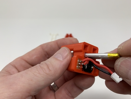
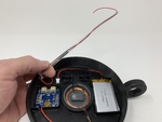
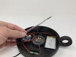
7) Slid all wires and the inductive charger receiver board up through the bottom of the threaded hole in "Lamp, Base.stl", then threaded the assembly into the lamp base.
8) Soldered one lead of the 100 ohm resistor to the red wire on the JST connector that came with the USB LiIon/LiPoly charger.
9) Soldered a 200mm length of red 26 AWG wire to the remaining lead of the 100 ohm resistor.
10) Insulted the exposed resistor wiring using electrical tape.
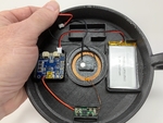
11) Applied double sided tape to the bottom of the inductive charger receiver board then pressed it into the assembly.
12) Soldered the red wire from the inductive charger receiver board to the USB LiIon/LiPoly "+" pin.
13) Soldered the black wire from the inductive charger receiver board to the USB LiIon/LiPoly "-" pin.
14) Applied double sided tape to the bottom of the USB LiIon/LiPoly board then pressed it into the assembly.
15) Applied double sided tape to one side of the LiPo battery then pressed it into the assembly.
16) Slid the 300mm black and 200mm red wires through the optional cut drinking straw.
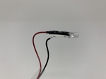
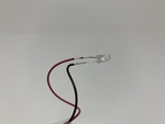
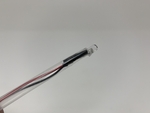
17) Straightened the leads on the LED.
18) Soldered the 300mm black wire to the LED cathode lead (the longer lead, closest to the flat on the LED).
19) Soldered the 200mm red wire to the LED anode lead (the shorter lead).
Insulated the LED anode lead with electrical tape.
20) Slid the LED assembly and wires back down the optional cut drinking straw until flush with the end.
21) Double checked all wiring.
22) Double checked all wiring again.
Test and Final Assembly.
To test the electronics, I performed the following steps:
1) Made sure the candle assembly was not on or near the base assembly.
2) Plugged the JST connector attached to the reed switch into the "LOAD" connector on the USB LiLon/LiPoly board.
3) Plugged the LiPo battery JST connector into the "BATT" connector on the USB LiIon/LiPoly board.
4) Checked to make sure the LED illuminated.
5) With the power supply unplugged, placed the candle assembly on the base assembly and made sure the LED extinguished.
6) Plugged in the power supply and made sure either the yellow "CHRG" or green "DONE" LEDs on the USB LiLon/LiPoly board illuminated.
For final assembly, I performed the following steps:
1) Snapped the flame lens from the tea lamp into "Lamp, Candle, Adapter.stl".
2) Threaded "Lamp, Candle.stl" into "Lamp, Cover.stl".
3) Slid the cut drinking straw assembly up through the bottom of the candle cover assembly, LED first, until the LED was clear of the hole in the top of the candle.
4) Pressed the LED into the lamp candle adapter assembly.
5) Pressed this assembly into the top of the candle.
6) Pressed the candle cover assembly into the candle base assembly.
And that's how I made "Inductive Candle".
I hope you enjoyed it!
Designer
Greg Zumwalt3d model description
An inductively charged candle and holder."Inductive Candle" is an inductively charged (similar to smart phone or watch "cable free" chargers) ca...ndle that automatically "lights" when removed from the charging base and "extinguishes" when returned to the charging base.
The base assembly contains an inductive transmitter and coil and a 12mm diameter by 3mm thick neodymium magnet.
The candle assembly contains an inductive coil and receiver, a lithium polymer battery charger, a lithium polymer battery, a 6mm diameter by 2mm thick neodymium magnet, a normally open reed switch, and a flickering LED.
When the candle assembly is removed from the base assembly, the neodymium magnet in the candle assembly activates the reed switch which illuminates the LED using the LiPo battery as the power source. When the candle assembly is returned to the base assembly, the neodymium magnet in the base assembly alters the magnetic field of the neodymium magnet in the candle assembly deactivating the reed switch and extinguishing the LED while the inductive charging system charges the LiPo battery. Since the charging system utilizes air coil induction which is not as efficient as cable charging, the design extinguishes the candle when the candle assembly is returned to the base assembly for charging.
I purchased the inductive charging system from Adafruit.com (I really like that place) who indicates the system will operate from 9 to 12vdc. When operated at 12vdc however, the inductive charging system generates heat that may be excessive for most PLA filaments. Using an IR thermometer I measured the temperature on "Base, Cover.stl" at 56° C (approximately 133° F) when using a 12vdc power source. Thus if you decide to use a 12vdc power source I recommend printing "Base, Cover.stl", "Base.stl" and "Lamp, Base Interface.stl" using Ultimaker CPE+ or equivalent filament having a higher temperature rating than PLA.
And as usual, I probably forgot a file or two or who knows what else, so if you have any questions, please do not hesitate to ask as I do make plenty of mistakes.
Designed using Autodesk Fusion 360 and Meshmixer 3.5.474, sliced using Cura 4.1 and printed in Ultimaker PLA and CPE+ filament on an Ultimaker 2+ Extended and an Ultimaker 3 Extended.
One final note, I receive no compensation in any form whatsoever for the use of any of the components and/or materials used in this design.
3d model print parameters
Purchase, Print and Prepare the Parts.I purchased (or salvaged) the following parts:
1) One Inductive Charger Set (https://www.adafruit.com/pro...duct/1407).
2) One USB LiIon/LiPoly charger (https://www.adafruit.com/product/259).
3) One LiPo Battery (https://www.adafruit.com/product/258).
4) One reed switch (2 by 12mm, Gikfun 20pcs Reed Switch Normally Open N/O Magnetic Induction Switch Electromagnetic for Arduino (Pack of 20pcs) EK1621x2, available on line).
5) One neodymium magnet (12mm diameter by 3mm thick, local hobby shop).
6) One neodymium magnet (6mm diameter by 2mm thick, local hobby shop).
7) One salvaged 9 - 12vdc 500ma power supply (note using a 12vdc power supply will decrease charging time at the expense of increased heat, while alternatively using a 9vdc power supply will increase charging time but with reduced heat).
8) One salvaged tea lamp LED (https://www.amazon.com/gp/product/B00T28FWVS/ref=ppx_yo_dt_b_asin_image_o00_s00?ie=UTF8&psc=1).
9) One salvaged 100 ohm resistor.
10) One white drinking straw ("borrowed" from a local restaurant) cut to 180mm in length This piece is optional in order to disguise the wiring in the candle if the candle is printed with translucent / transparent material.
Parts I Printed:
I printed one each of all parts at .15mm layer height, 20% infill. Since the inductive charging system generates heat, I printed "Base, Cover.stl", "Base.stl" and "Lamp, Base Interface.stl" using Ultimaker CPE+ filament. The remaining parts were printed in Ultimaker PLA filament.
Assemble the Charging Base.
To assemble the Charging Base, I performed the following steps:
1) Carefully placed the two magnet faces together, then marked an "X" on the outside faces with an indelible ink pen.
2) Desoldered and removed the red and black wires from the inductive charger transmitter board.
3) Slid the inductive charger transmitter board down through the slot in "Base.stl".
4) Pressed the inductive charger coil into the ring in the top of the base, aligning the wires from the coil to the inductive charger transmitter board with the slot.
5) Slid the power supply wires into the hole in the side of the base.
6) Tied a knot in the power supply wires for strain relief.
7) Applied double sided tape to the bottom of the inductive charger transmitter board.
8) Pressed the inductive charger transmitter board into the base.
9) Soldered the positive ("+") power supply wire to the inductive charger transmitter board "+" pin.
10) Soldered the negative ("-") power supply wire to the inductive charger transmitter board "-" pin.
11) Pressed the 12mm diameter by 3mm thick neodymium magnet into "Base, Cover.stl" such that the "X" mark is visible.
12) Pressed the base cover in place on top of the base.
Disassemble the Tea Lamp.
The design uses the flickering LED and the flame lens from the tea lamp I salvaged. To obtain these parts, disassembly of the tea lamp is required. To disassemble the tea lamp, I performed the following steps:
1) Removed the battery cover and battery from the tea lamp.
2) Used a small screwdriver to remove the cover from tea lamp.
3) Used a small screwdriver to remove the lens from the tea lamp cover.
4) Removed the LED and switch from the tea lamp base.
5) Removed the switch from the LED.
Assemble the Candle Electronics.
To assemble the candle electronics, I performed the following steps:
1) Pressed the 6mm diameter by 2mm thick neodymium magnet into the hole in "Lamp, Candle, Interface.stl" such that the "X" mark (the mark made in step 2) is visible.
2) Pressed the inductive charger receiver coil into this assembly.
3) Slid the reed switch into the this assembly.
4) Using locking forceps on each lead (NOT THE GLASS), I carefully centered the read switch then bent the reed switch leads as shown. If you do not use locking forceps or an equivalent method, you may break the reed switch glass and permanently damaging the reed switch.
5) Soldered a 300mm length of black 26 AWG wire to one contact of the read switch.
6) Soldered the black wire on the JST connector that came with the USB LiIon/LiPoly charger to the remaining reed switch contact.
7) Slid all wires and the inductive charger receiver board up through the bottom of the threaded hole in "Lamp, Base.stl", then threaded the assembly into the lamp base.
8) Soldered one lead of the 100 ohm resistor to the red wire on the JST connector that came with the USB LiIon/LiPoly charger.
9) Soldered a 200mm length of red 26 AWG wire to the remaining lead of the 100 ohm resistor.
10) Insulted the exposed resistor wiring using electrical tape.
11) Applied double sided tape to the bottom of the inductive charger receiver board then pressed it into the assembly.
12) Soldered the red wire from the inductive charger receiver board to the USB LiIon/LiPoly "+" pin.
13) Soldered the black wire from the inductive charger receiver board to the USB LiIon/LiPoly "-" pin.
14) Applied double sided tape to the bottom of the USB LiIon/LiPoly board then pressed it into the assembly.
15) Applied double sided tape to one side of the LiPo battery then pressed it into the assembly.
16) Slid the 300mm black and 200mm red wires through the optional cut drinking straw.
17) Straightened the leads on the LED.
18) Soldered the 300mm black wire to the LED cathode lead (the longer lead, closest to the flat on the LED).
19) Soldered the 200mm red wire to the LED anode lead (the shorter lead).
Insulated the LED anode lead with electrical tape.
20) Slid the LED assembly and wires back down the optional cut drinking straw until flush with the end.
21) Double checked all wiring.
22) Double checked all wiring again.
Test and Final Assembly.
To test the electronics, I performed the following steps:
1) Made sure the candle assembly was not on or near the base assembly.
2) Plugged the JST connector attached to the reed switch into the "LOAD" connector on the USB LiLon/LiPoly board.
3) Plugged the LiPo battery JST connector into the "BATT" connector on the USB LiIon/LiPoly board.
4) Checked to make sure the LED illuminated.
5) With the power supply unplugged, placed the candle assembly on the base assembly and made sure the LED extinguished.
6) Plugged in the power supply and made sure either the yellow "CHRG" or green "DONE" LEDs on the USB LiLon/LiPoly board illuminated.
For final assembly, I performed the following steps:
1) Snapped the flame lens from the tea lamp into "Lamp, Candle, Adapter.stl".
2) Threaded "Lamp, Candle.stl" into "Lamp, Cover.stl".
3) Slid the cut drinking straw assembly up through the bottom of the candle cover assembly, LED first, until the LED was clear of the hole in the top of the candle.
4) Pressed the LED into the lamp candle adapter assembly.
5) Pressed this assembly into the top of the candle.
6) Pressed the candle cover assembly into the candle base assembly.
And that's how I made "Inductive Candle".
I hope you enjoyed it!