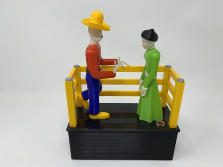
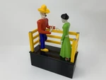
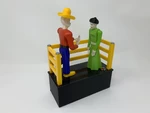
Última cita. en 3D para imprimir

13623 Visualizaciones 1 Me gusta 0 Descargas realizadas Descarga aqui la pieza desde 3dforprint
https://youtu.be/3hzI6N0xRec
estaba jugando en el momento en que le pidió a mi madre que se casara con él, y, bueno, ella dijo que s...í! Este modelo, "Última fecha", es en recuerdo de ellos y su matrimonio hasta su muerte.
Como de costumbre, probablemente olvidé un archivo o dos o quién sabe qué más, así que si tiene alguna pregunta, no dude en comentar, ya que cometo muchos errores.
Diseñado usando Autodesk Fusion 360, cortado usando Ultimaker Cura 4.7.0, e impreso en 3D en PLA en Ultimaker S5s.
Comprar las siguientes partes:
* Un motor de engranaje N20 100RPM 6VDC.
* Un soporte de batería 2AAA con interruptor de encendido / apa...gado.
* Dos pilas AAA.
* Un interruptor pulsador momentáneo normalmente abierto (debe caber un agujero de 13.00 mm).
* Un interruptor de palanca micro (buscar " CYT1073")
* Treinta y seis pulgadas de alambre de música de 1,15 mm (3/64") de diámetro.
* Dos imanes de neodimio de 3 mm (diámetro) por 1,5 mm (grosor).
* Dos imanes de neodimio de 6 mm (diámetro) por 1,5 mm (grosor).
* Cuatro tornillos de casquillo M2. 5 por 16m m.
* Cuatro tuercas M2. 5.
El archivo adjunto " Partes.pdf " contiene el nombre, la cantidad, el relleno, la altura de la capa y el soporte de todas las partes impresas en 3D que imprimí para este mecanismo. Note parts with a".3MF " extensión son impresiones de extrusión doble.
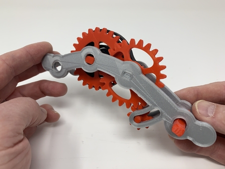
Este mecanismo es una impresión y ensamblaje de alta precisión que utiliza a veces piezas impresas en 3D de precisión muy pequeñas en espacios confinados con una alineación altamente precisa. Imprimí los engranajes, palancas, brazos, levas y ruedas usando el Ultimaker Cura 4.7.0 "Perfil de ingeniería" en mi Ultimaker S5s, que proporciona una tolerancia altamente precisa que requiere un mínimo de recorte, limado, taladrado o lijado. Sin embargo, antes del montaje, todavía prueba ajustado y recortado, archivado, perforado, lijado, etc. todas las partes necesarias para el movimiento suave de superficies en movimiento, y ajuste ajustado para superficies no móviles. Dependiendo de la máquina de cortar, la impresora, la configuración de la impresora y los colores que elija, puede ser necesario más o menos recortar, archivar, taladrar y/o lijar para recrear con éxito este modelo. Archivé cuidadosamente todos los bordes que entraron en contacto con la placa de construcción para estar absolutamente seguro de que toda la placa de construcción "supura" se elimina y que todos los bordes son lisos utilizando pequeños archivos de joyeros y mucha paciencia para realizar este paso.
Este mecanismo también utiliza ensamblaje roscado, por lo que utilicé un juego de grifos y troqueles (6 mm por 1, 8 mm por 1,25) si era necesario para la limpieza de roscas.
Pushrods.
Para crear Sus pushrods, realicé las siguientes tareas:
* Corte un cable de música de 160 mm de longitud.
* Creó una curva de 90 grados, de 15 mm de largo, en un extremo de la longitud de corte del cable de música.
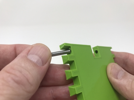
* Coloca la curva de 15mm en el agujero en " Plantilla, Su, Varilla de empuje.stl".
* Creó una curva de 90 grados en el extremo restante de la longitud de corte del cable de música.
* Corte la última curva de 90 grados a 5.5 mm de longitud.
* Se ha quitado el cable de la plantilla.
* Lija los extremos cortados lisos.
Para crear Su pushrod, realicé las siguientes tareas:
* Corte un cable de música de 150 mm de longitud.
* Creó una curva de 90 grados, de 10 mm de largo, en un extremo de la longitud de corte del cable de música.
* Slid the straight end of this wire into the slot in "Jig, Hers, Pushrod.stl", luego colocó la curva de 10 mm en el agujero en la plantilla.
* Doblado el extremo recto hasta 90 grados.
* Corte esta curva a 3 mm de longitud.
* Se ha quitado el cable de la plantilla.
* Lija los extremos cortados lisos.
Basar.
Para montar la base, realicé los siguientes pasos:
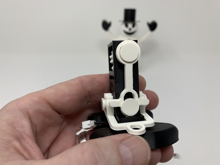
* Acoplado los dos interruptores de palanca micro a la base utilizando los pernos y tuercas de 2,5 mm.
* Placed " Arm, His, Pushrods.stl " en el conjunto de base.
* Slid " Yoke, Arm.stl " en el conjunto de base.
* Deslizó uno de sus pushrods en el conjunto de base base, luego colocó la curva larga en el yugo del brazo.
* Repitió este paso con el resto de su varilla.
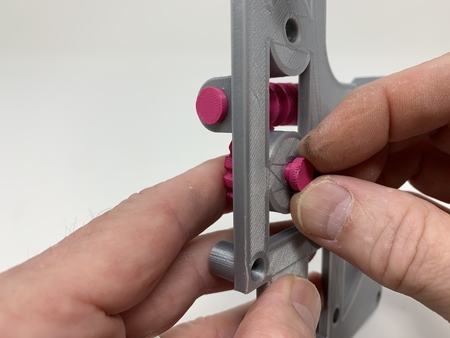
* Deslizado " Yugo, Brazo, Imán, Con Morar.stl " en el conjunto de base.
* Posicionado " Engranaje, Yugo, Brazo, Imán (2m 20t).stl "y asegurado en su lugar con" Eje Para Engranajes (2m 20t).stl".
* Coloque el pasador en el engranaje del brazo en la ranura del brazo del imán.
* Roscado " Pin, Yugo, Brazo.stl " en el brazo de yugo de tal manera que el pasador se colocó en el brazo, su, ranura de pushrods.
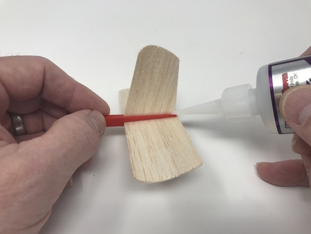
* Encolado " Bota, Izquierda.slt "en la pierna izquierda de" Piernas.stl", y " Boot, Correcto.en la pierna derecha.
* Deslice el conjunto de la pierna (pierna derecha) sobre los pushrods (pushrods en las ranuras en la pierna derecha) y el yugo, el brazo, el imán, con dwell, coloquio pequeños puntos de pegado en la ranura derecha del zapato en la base, luego presiona el conjunto de la pierna en su posición asegurándose de que sea perpendicular a la base.
* Posicionado " Engranaje, Yugo, Brazo (2m 20t).stl "en el conjunto base y asegurado en su lugar con" Engranaje, Eje, Engranaje, Yugo, Brazo (2m 10t).stl".
* Posicionado " Engranaje, Rueda loca (2m 20t).stl "en el conjunto de base, se aseguró de los pasadores en" Engranaje, Yugo, Brazo, Imán (2m 20t).stl " y " Engranaje, Eje, Engranaje, Yugo, Brazo (2m 10t).stl " and " Gear, Idler (2m 20t).los lóbulos de leva stl "se alinearon como se muestra, luego se aseguraron en su lugar utilizando el eje" Para la rueda Loca Del Engranaje (2m 20t).stl".
* Positioned " Arm, Hers, Head.stl "en el conjunto base y asegurado en su lugar usando" Eje, de ella, Brazo, Cabeza.stl".
Él.
Para montarlo, realicé los siguientes pasos:
* Glued " Belt, His.stl", a " Torso.stl".
* Hebilla pegada.stl " al cinturón.
* Pressed " Hand, His, Right.stl " en " Brazo, Su, Derecha.stl".
* Presionado un imán de 3mm en la mano.
* Presionado sobre imán de 6mm en " Soporte, Imán.stl".
* Adjunto el soporte del imán a " Yugo, Brazo, Imán, Con Dwell.stl "usando" Eje, Soporte, Imán.stl".
* Colocado " Eje, Brazo, Derecha.stl " en los extremos de su varilla.
* Deslizar el conjunto del torso sobre el conjunto de las piernas y pegarlo en su posición.
* Giró los engranajes hasta que el soporte del imán estuviera en su posición más baja, luego usó un punzón plano para sostener el eje del brazo derecho en su posición, pegó el conjunto del brazo derecho en el eje del brazo derecho, asegurándose de que estuviera presionado completamente en su posición en el eje.
* Slid " Head, His.3mf " en el torso y pegado en su lugar.
* Presionado un imán de 3mm en " Sombrero, Suyo.stl " tal que atraerá a la mano.
* Presiona un imán de 6 mm en el conjunto del sombrero de tal manera que se atraiga al soporte del imán.
* Coloca el conjunto del sombrero en la cabeza.
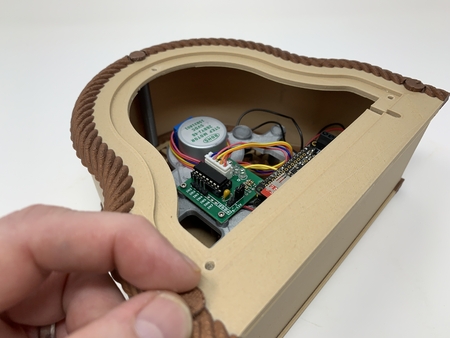
Cableado.
Cableé el modelo usando los siguientes pasos:
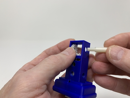
* Se instaló el interruptor de botón momentáneo en el conjunto de base utilizando las tuercas y arandelas incluidas.
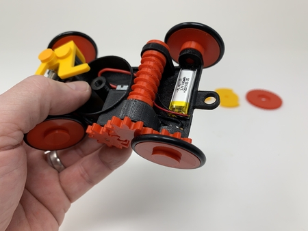
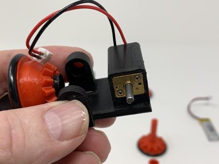
* Instalado el motor en la base.
* Prensado " Engranaje, Motor.stl (2m 10t).stl "en el eje del motor, alineando el engranaje del motor con" Engranaje, Yugo, Brazo (2m 20t).stl".
* Soldó un cable entre el terminal común ("C") del interruptor de límite lateral al terminal común ("C") del interruptor de límite delantero.
* Soldó un cable entre el terminal lateral del interruptor de límite normalmente cerrado ("NC") al terminal frontal del interruptor de límite normalmente cerrado ("NC").
* Soldó un cable entre el terminal común ("C") del interruptor de límite delantero a un terminal del interruptor pulsador momentáneo.
* Soldó un cable entre el terminal del interruptor de límite delantero normalmente cerrado ("NC") al terminal restante del interruptor pulsador momentáneo.
* Soldó el cable rojo del soporte de la batería al terminal " + " del motor.
* Soldó el cable negro del soporte de la batería a un terminal del interruptor pulsador momentáneo.
* Soldó un cable entre el otro terminal del interruptor pulsador momentáneo al terminal " - " del motor.
Ella.
Para montar, Ella, realicé los siguientes pasos:
* Vestido Pegado, Cinturón.vestido stl "to", Falda.stl".
* Pegado el conjunto del vestido al conjunto de la base.
* Usando alicates de punta de aguja, posicionados " Leva, de ella, Cabeza.stl " en " Vestido, Torso.stl " tal que el pequeño agujero se colocó hacia atrás.
* Slid " Axle, Hers, Cam.stl " a través de la abertura del brazo izquierdo, agujero de la leva, entonces hacia fuera la abertura del brazo del lado derecho.
* Glued " Head, Hers, Hair.stl " to " Head, Hers, Head.stl".
* Utiliza plumas de tinta indeleble, color añadido a sus ojos, labios.
* Pegó el conjunto de la cabeza al brazo de leva asegurándose de que la cabeza girara fácilmente.
* Insertó la curva de 90 grados de 10 mm a través del lado derecho del orificio en la leva.
* Deslice la varilla de empuje en la guía del vestido, deslice el conjunto del torso completamente hacia abajo y pegue el conjunto al conjunto del vestido.
* Insertó la curva de 3 mm de 90 grados en el agujero en " Brazo, El suyo, Cabeza.stl".
* Glued " Arm, Hers, Right.stl " al extremo derecho del eje de leva.
* Glued " Hand, Hers.hasta el final de su brazo derecho.
* Repitió los dos pasos anteriores para el brazo izquierdo.
Montaje Final.
Para el montaje final, realicé los siguientes pasos:
* Adjunta la batería a " Base, Falda.stl " usando cinta de doble cara.
* Deslizó el conjunto de falda de base sobre las piernas en el conjunto de base, luego aseguró la falda a la base usando cuatro " Perno, Base, Falda.stl".
* Attached " Fence, Left.stl " y " Fence, Correcto.stl "a la base usando cuatro" Perno, Cerca.stl".
* Posicionado tres " Cerca, Carril.stl " en las ranuras entre los extremos de la valla izquierda y derecha y pegado en su lugar.
* Pressed " Hand, His, Left.stl "onto" Brazo, El Suyo, Izquierda.stl " y pegado en su lugar.
* Pegó el conjunto del brazo izquierdo al hombre izquierdo.
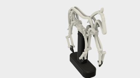
Y así es como imprimí y ensamblé la última Fecha en 3D.
Espero que te haya gustado!
Diseñador
Greg ZumwaltDescripción del modelo 3d
homenaje.https://youtu.be/3hzI6N0xRec
estaba jugando en el momento en que le pidió a mi madre que se casara con él, y, bueno, ella dijo que s...í! Este modelo, "Última fecha", es en recuerdo de ellos y su matrimonio hasta su muerte.
Como de costumbre, probablemente olvidé un archivo o dos o quién sabe qué más, así que si tiene alguna pregunta, no dude en comentar, ya que cometo muchos errores.
Diseñado usando Autodesk Fusion 360, cortado usando Ultimaker Cura 4.7.0, e impreso en 3D en PLA en Ultimaker S5s.
Parametros de impresión 3d
Parte.Comprar las siguientes partes:
* Un motor de engranaje N20 100RPM 6VDC.
* Un soporte de batería 2AAA con interruptor de encendido / apa...gado.
* Dos pilas AAA.
* Un interruptor pulsador momentáneo normalmente abierto (debe caber un agujero de 13.00 mm).
* Un interruptor de palanca micro (buscar " CYT1073")
* Treinta y seis pulgadas de alambre de música de 1,15 mm (3/64") de diámetro.
* Dos imanes de neodimio de 3 mm (diámetro) por 1,5 mm (grosor).
* Dos imanes de neodimio de 6 mm (diámetro) por 1,5 mm (grosor).
* Cuatro tornillos de casquillo M2. 5 por 16m m.
* Cuatro tuercas M2. 5.
El archivo adjunto " Partes.pdf " contiene el nombre, la cantidad, el relleno, la altura de la capa y el soporte de todas las partes impresas en 3D que imprimí para este mecanismo. Note parts with a".3MF " extensión son impresiones de extrusión doble.
Este mecanismo es una impresión y ensamblaje de alta precisión que utiliza a veces piezas impresas en 3D de precisión muy pequeñas en espacios confinados con una alineación altamente precisa. Imprimí los engranajes, palancas, brazos, levas y ruedas usando el Ultimaker Cura 4.7.0 "Perfil de ingeniería" en mi Ultimaker S5s, que proporciona una tolerancia altamente precisa que requiere un mínimo de recorte, limado, taladrado o lijado. Sin embargo, antes del montaje, todavía prueba ajustado y recortado, archivado, perforado, lijado, etc. todas las partes necesarias para el movimiento suave de superficies en movimiento, y ajuste ajustado para superficies no móviles. Dependiendo de la máquina de cortar, la impresora, la configuración de la impresora y los colores que elija, puede ser necesario más o menos recortar, archivar, taladrar y/o lijar para recrear con éxito este modelo. Archivé cuidadosamente todos los bordes que entraron en contacto con la placa de construcción para estar absolutamente seguro de que toda la placa de construcción "supura" se elimina y que todos los bordes son lisos utilizando pequeños archivos de joyeros y mucha paciencia para realizar este paso.
Este mecanismo también utiliza ensamblaje roscado, por lo que utilicé un juego de grifos y troqueles (6 mm por 1, 8 mm por 1,25) si era necesario para la limpieza de roscas.
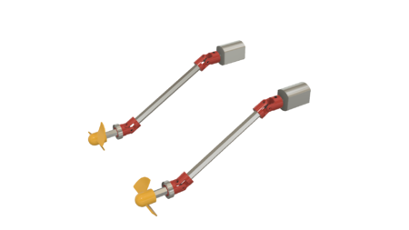
Pushrods.
Para crear Sus pushrods, realicé las siguientes tareas:
* Corte un cable de música de 160 mm de longitud.
* Creó una curva de 90 grados, de 15 mm de largo, en un extremo de la longitud de corte del cable de música.
* Coloca la curva de 15mm en el agujero en " Plantilla, Su, Varilla de empuje.stl".
* Creó una curva de 90 grados en el extremo restante de la longitud de corte del cable de música.
* Corte la última curva de 90 grados a 5.5 mm de longitud.
* Se ha quitado el cable de la plantilla.
* Lija los extremos cortados lisos.
Para crear Su pushrod, realicé las siguientes tareas:
* Corte un cable de música de 150 mm de longitud.
* Creó una curva de 90 grados, de 10 mm de largo, en un extremo de la longitud de corte del cable de música.
* Slid the straight end of this wire into the slot in "Jig, Hers, Pushrod.stl", luego colocó la curva de 10 mm en el agujero en la plantilla.
* Doblado el extremo recto hasta 90 grados.
* Corte esta curva a 3 mm de longitud.
* Se ha quitado el cable de la plantilla.
* Lija los extremos cortados lisos.
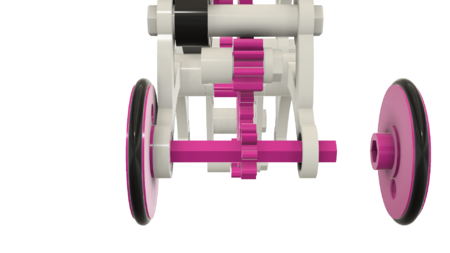
Basar.
Para montar la base, realicé los siguientes pasos:
* Acoplado los dos interruptores de palanca micro a la base utilizando los pernos y tuercas de 2,5 mm.
* Placed " Arm, His, Pushrods.stl " en el conjunto de base.
* Slid " Yoke, Arm.stl " en el conjunto de base.
* Deslizó uno de sus pushrods en el conjunto de base base, luego colocó la curva larga en el yugo del brazo.
* Repitió este paso con el resto de su varilla.
* Deslizado " Yugo, Brazo, Imán, Con Morar.stl " en el conjunto de base.
* Posicionado " Engranaje, Yugo, Brazo, Imán (2m 20t).stl "y asegurado en su lugar con" Eje Para Engranajes (2m 20t).stl".
* Coloque el pasador en el engranaje del brazo en la ranura del brazo del imán.
* Roscado " Pin, Yugo, Brazo.stl " en el brazo de yugo de tal manera que el pasador se colocó en el brazo, su, ranura de pushrods.
* Encolado " Bota, Izquierda.slt "en la pierna izquierda de" Piernas.stl", y " Boot, Correcto.en la pierna derecha.
* Deslice el conjunto de la pierna (pierna derecha) sobre los pushrods (pushrods en las ranuras en la pierna derecha) y el yugo, el brazo, el imán, con dwell, coloquio pequeños puntos de pegado en la ranura derecha del zapato en la base, luego presiona el conjunto de la pierna en su posición asegurándose de que sea perpendicular a la base.
* Posicionado " Engranaje, Yugo, Brazo (2m 20t).stl "en el conjunto base y asegurado en su lugar con" Engranaje, Eje, Engranaje, Yugo, Brazo (2m 10t).stl".
* Posicionado " Engranaje, Rueda loca (2m 20t).stl "en el conjunto de base, se aseguró de los pasadores en" Engranaje, Yugo, Brazo, Imán (2m 20t).stl " y " Engranaje, Eje, Engranaje, Yugo, Brazo (2m 10t).stl " and " Gear, Idler (2m 20t).los lóbulos de leva stl "se alinearon como se muestra, luego se aseguraron en su lugar utilizando el eje" Para la rueda Loca Del Engranaje (2m 20t).stl".
* Positioned " Arm, Hers, Head.stl "en el conjunto base y asegurado en su lugar usando" Eje, de ella, Brazo, Cabeza.stl".
Él.
Para montarlo, realicé los siguientes pasos:
* Glued " Belt, His.stl", a " Torso.stl".
* Hebilla pegada.stl " al cinturón.
* Pressed " Hand, His, Right.stl " en " Brazo, Su, Derecha.stl".
* Presionado un imán de 3mm en la mano.
* Presionado sobre imán de 6mm en " Soporte, Imán.stl".
* Adjunto el soporte del imán a " Yugo, Brazo, Imán, Con Dwell.stl "usando" Eje, Soporte, Imán.stl".
* Colocado " Eje, Brazo, Derecha.stl " en los extremos de su varilla.
* Deslizar el conjunto del torso sobre el conjunto de las piernas y pegarlo en su posición.
* Giró los engranajes hasta que el soporte del imán estuviera en su posición más baja, luego usó un punzón plano para sostener el eje del brazo derecho en su posición, pegó el conjunto del brazo derecho en el eje del brazo derecho, asegurándose de que estuviera presionado completamente en su posición en el eje.
* Slid " Head, His.3mf " en el torso y pegado en su lugar.
* Presionado un imán de 3mm en " Sombrero, Suyo.stl " tal que atraerá a la mano.
* Presiona un imán de 6 mm en el conjunto del sombrero de tal manera que se atraiga al soporte del imán.
* Coloca el conjunto del sombrero en la cabeza.
Cableado.
Cableé el modelo usando los siguientes pasos:
* Se instaló el interruptor de botón momentáneo en el conjunto de base utilizando las tuercas y arandelas incluidas.
* Instalado el motor en la base.
* Prensado " Engranaje, Motor.stl (2m 10t).stl "en el eje del motor, alineando el engranaje del motor con" Engranaje, Yugo, Brazo (2m 20t).stl".
* Soldó un cable entre el terminal común ("C") del interruptor de límite lateral al terminal común ("C") del interruptor de límite delantero.
* Soldó un cable entre el terminal lateral del interruptor de límite normalmente cerrado ("NC") al terminal frontal del interruptor de límite normalmente cerrado ("NC").
* Soldó un cable entre el terminal común ("C") del interruptor de límite delantero a un terminal del interruptor pulsador momentáneo.
* Soldó un cable entre el terminal del interruptor de límite delantero normalmente cerrado ("NC") al terminal restante del interruptor pulsador momentáneo.
* Soldó el cable rojo del soporte de la batería al terminal " + " del motor.
* Soldó el cable negro del soporte de la batería a un terminal del interruptor pulsador momentáneo.
* Soldó un cable entre el otro terminal del interruptor pulsador momentáneo al terminal " - " del motor.
Ella.
Para montar, Ella, realicé los siguientes pasos:
* Vestido Pegado, Cinturón.vestido stl "to", Falda.stl".
* Pegado el conjunto del vestido al conjunto de la base.
* Usando alicates de punta de aguja, posicionados " Leva, de ella, Cabeza.stl " en " Vestido, Torso.stl " tal que el pequeño agujero se colocó hacia atrás.
* Slid " Axle, Hers, Cam.stl " a través de la abertura del brazo izquierdo, agujero de la leva, entonces hacia fuera la abertura del brazo del lado derecho.
* Glued " Head, Hers, Hair.stl " to " Head, Hers, Head.stl".
* Utiliza plumas de tinta indeleble, color añadido a sus ojos, labios.
* Pegó el conjunto de la cabeza al brazo de leva asegurándose de que la cabeza girara fácilmente.
* Insertó la curva de 90 grados de 10 mm a través del lado derecho del orificio en la leva.
* Deslice la varilla de empuje en la guía del vestido, deslice el conjunto del torso completamente hacia abajo y pegue el conjunto al conjunto del vestido.
* Insertó la curva de 3 mm de 90 grados en el agujero en " Brazo, El suyo, Cabeza.stl".
* Glued " Arm, Hers, Right.stl " al extremo derecho del eje de leva.
* Glued " Hand, Hers.hasta el final de su brazo derecho.
* Repitió los dos pasos anteriores para el brazo izquierdo.
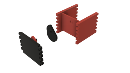
Montaje Final.
Para el montaje final, realicé los siguientes pasos:
* Adjunta la batería a " Base, Falda.stl " usando cinta de doble cara.
* Deslizó el conjunto de falda de base sobre las piernas en el conjunto de base, luego aseguró la falda a la base usando cuatro " Perno, Base, Falda.stl".
* Attached " Fence, Left.stl " y " Fence, Correcto.stl "a la base usando cuatro" Perno, Cerca.stl".
* Posicionado tres " Cerca, Carril.stl " en las ranuras entre los extremos de la valla izquierda y derecha y pegado en su lugar.
* Pressed " Hand, His, Left.stl "onto" Brazo, El Suyo, Izquierda.stl " y pegado en su lugar.
* Pegó el conjunto del brazo izquierdo al hombre izquierdo.
Y así es como imprimí y ensamblé la última Fecha en 3D.
Espero que te haya gustado!