Mouvement perpétuel da vinci style iii 3d pour imprimer

7960 Vues 1 Goûts 0 Téléchargements Téléchargez ici la pièce à partir de 3dforprint
https://youtu.be/guqpy8zpemy
https://youtu.be/ycVoido6hhg
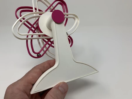
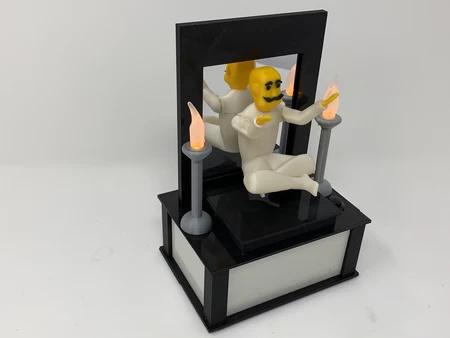
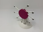
"Perpetual Motion da Vinci Style III" est le troisième "Machine d...e mouvement perpétuel" dans ma série de modèles "Roue surbancés" de M. Da Vinci, les deux derniers conçus pour un environnement de classe. On m'a demandé de créer ces deux nouveaux ajouts (plus quelques autres) afin d'inspirer la discussion en classe du travail de M. Da Vinci, et j'étais ravi de convertir ses conceptions bidimensionnelles en ces modèles tridimensionnels stylisés pour la salle de classe!
Comme dans ma version précédente "Perpetual Motion DaVinci Style II", "Perpetual Motion" commence lorsque le modèle est incliné vers l'arrière, ce qui fait activer un aimant pour activer un interrupteur à roseau qui active à son tour un moteur qui tourne la roue trop calorée via une transmission en caoutchouc. Et le "mouvement perpétuel" se termine lorsque la batterie expire, la bande de caoutchouc se casse, le moteur donne, ou en inclinant simplement le modèle vers l'avant et en tapant sur le dos près de l'interrupteur à anche pour désengager l'aimant. En d'autres termes, c'est toujours une illusion.
Comme d'habitude, j'ai probablement oublié un fichier ou deux ou qui sait quoi d'autre, donc si vous avez des questions, n'hésitez pas à demander car je fais beaucoup d'erreurs. Conçu en utilisant Autodesk Fusion 360, tranché à l'aide de Cura 4.0 et imprimé dans PLA sur un Ultimaker 2+ étendu et un Ultimaker 3 étendu.
J'ai acheté les parties suivantes:
1) Une batterie (https://www.adafruit.com/product/258).
2) Un câble... JST PH 2-PIN - En-tête masculin 200 mm (https://www.adafruit.com/product/3814).
3) Un interrupteur à roseau (2 par 12 mm, interrupteur de roseau Gikfun 20pcs ouvre normalement le commutateur d'induction magnétique N / S électromagnétique pour Arduino (pack de 20 pcs) EK1621X2, disponible en ligne).
4) Un moteur d'engrenage de 100 tr / min (100 tr / min DC 6V 2,5 kg micro de vitesse de vitesse de vitesse de vitesse de réduction du moteur, disponible en ligne).
5) un élastique (75 mm par 7 mm).
6) Roulements à billes de vingt mm (quincaillerie locale).
7) Un aimant en néodyme de 12 mm par 3 mm (magasin de loisirs local).
J'ai imprimé les parties suivantes à une hauteur de couche de 0,15 mm et à 20% de remplissage.
1) dix "arm.stl".
2) un "back.stl".
3) une "base.stl".
4) Un "Holder, Reed, Switch.stl".
5) une "poulie, moteur.stl".
6) Une "poulie, roue.stl".
7) Une "roue, inner.stl".
8) une "roue, exter.stl".
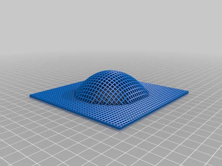
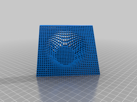
"Base.stl" doit être imprimé avec un bord intérieur et extérieur et des supports. J'ai inclus une capture d'écran Cura 4.0 de l'aperçu de la base avec le bord et les supports. Le matériau bleu apparaissant dans la capture d'écran indique comment les bords et les supports doivent apparaître.
Les pièces restantes ne nécessitent pas de bords ou de supports.
Avant l'assemblage, je teste l'ajustement et le taillage, le dossier, le poncé, etc. Toutes les pièces si nécessaires pour le mouvement lisse des surfaces mobiles et l'ajustement serré pour les surfaces non mobiles. Selon les couleurs que vous avez choisies, votre modèle d'imprimante et les paramètres de votre imprimante, plus ou moins de coupe, de dépôt et / ou de ponçage peuvent être nécessaires. J'ai soigneusement déposé tous les bords qui ont contacté la plaque de construction pour rendre absolument certain que toutes les plaques de construction "suintement" ont été retirées et que tous les bords sont lisses. J'ai utilisé de petits fichiers de bijoutiers et beaucoup de patience pour effectuer cette étape. Le modèle utilise des composants filetés de 8 mm par 1,25, donc un jeu de robinet et de matrice peut être nécessaire pour nettoyer les pièces filetées.
Préparez l'électronique.
Pour préparer l'électronique, j'ai effectué les étapes suivantes:
1) Souder le fil rouge du câble JST PH à 2 broches à la borne "+" et le fil noir du câble JST Ph à 2 broches au moteur "-" Terminal.
2) À l'heure actuelle, j'ai branché la batterie dans le connecteur du moteur et je me suis assuré que l'arbre du moteur tournait dans le sens des aiguilles d'une montre à partir de l'extrémité de l'arbre du moteur du moteur. Sinon, j'ai inversé les fils. Dans les deux cas, j'ai ensuite débranché la batterie.
3) Plié soigneusement plié une extrémité de l'interrupteur à roseau comme indiqué.
4) Coupez le fil noir du câble JST PH à 2 broches au milieu puis enlevant et en licencie les extrémités coupées.
5) Souder une extrémité en conserve du fil noir à une extrémité de l'interrupteur à roseau.
6) Souder l'extrémité en conserve restante du fil noir à l'extrémité restante de l'interrupteur à anche.
Assemblez la roue surbalancée.
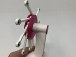
Dans ce modèle, les roulements à billes de 8 mm servent un double objectif. Chacun des dix bras de roue a deux prises conçues pour "cage" les roulements à billes. Le roulement à billes extérieur dans sa prise est utilisé comme masse pour la roue surbalancée, et le roulement à billes intérieur dans sa prise est utilisé comme essieu permettant au bras de pivoter librement. Pour assembler les bras et la roue surbalancée, j'ai effectué les étapes suivantes:
1) À l'aide d'un maillet en caoutchouc, j'ai appuyé deux roulements à billes de 8 mm (un chacun) dans les deux prises dans un "bras".
2) Une fois installé, j'ai testé chaque roulement à billes pour m'assurer qu'il pivotait librement dans sa prise.
3) J'ai répété ce processus pour les neuf bras restants.
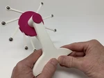
4) J'ai ensuite positionné les assemblages du bras dans les fossettes de "Wheel, exter.stl".
5) Enfin, j'ai sécurisé "roue, intérieur.stl" sur l'ensemble de roue externe à l'aide d'un maillet en caoutchouc et d'une douille profonde de 13 mm.
Assemblage final et fonctionnement.
Pour l'assemblage final du modèle, j'ai effectué les étapes suivantes:
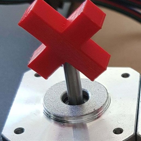
1) Appuyez sur "Poulle, Motor.stl" sur l'arbre du moteur.
2) Gliez l'aimant de néodyme de 12 mm par 3 mm dans la fente du guide de l'aimant dans "Base.stl".
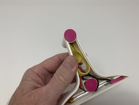
3) Faire glisser la batterie dans la fente de la batterie dans l'ensemble de base.
4) Appuyez sur l'ensemble du moteur dans la fente du moteur dans l'ensemble de base tout en orientant soigneusement les fils pour s'adapter dans la fente des fils du moteur.
5) Gliez l'interrupteur à anche dans le support de l'interrupteur à anche, puis appuyez sur l'assemblage en position dans l'assemblage de base.
5) Connecté la batterie au bouchon du moteur.
7) a testé l'assemblage en le penchant en arrière de telle sorte que l'aimant se glissait vers l'interrupteur à anche et activait le moteur et a noté que le moteur tournait dans le sens des aiguilles d'une montre.
8) Arrêt de l'assemblage en le penchant vers l'avant et en tapant sur le coin de l'assemblage de base jusqu'à ce que l'aimant se glisse loin de l'interrupteur à roseau.
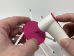
9) Positionné la bande de caoutchouc dans l'assemblage.
10) Pour la lubrification lors de l'insertion, j'ai humidifié "Poulle, Wheel.stl" avec de l'eau du robinet, puis je l'ai glissée en position de telle sorte que la bande de caoutchouc est autour de la plus petite section d'arbre de la poulie de roue.
11) Fidèrent l'assemblage de la roue sur la poulie de la roue, puis s'assurait que l'ensemble de roue tournait facilement.
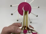
12) a étiré le caoutchouc autour de la poulie du moteur.
13) a été absolument certain qu'aucun du câblage ne pouvait entrer en contact avec les pièces mobiles. Pressé "back.stl" dans l'assemblage de base.
Pour démarrer le modèle, inclinez-le vers l'arrière jusqu'à ce que l'aimant active l'interrupteur à anche. Pour arrêter le modèle, inclinez-le vers l'avant et appuyez doucement sur le dos près de l'interrupteur à anche pour séparer l'aimant de l'interrupteur à anche. Avec la pratique, j'ai pu incliner légèrement le modèle vers l'arrière et donner l'apparence de faire tourner la roue à contre-courant pour démarrer le modèle.
Et c'est ainsi que j'ai imprimé et assemblé "Perpetual Motionda Vinci Style III".
J'espère que vous l'avez apprécié!
Designer
Greg ZumwaltDescription du modèle 3D
Un autre design Da Vinci.https://youtu.be/guqpy8zpemy
https://youtu.be/ycVoido6hhg
"Perpetual Motion da Vinci Style III" est le troisième "Machine d...e mouvement perpétuel" dans ma série de modèles "Roue surbancés" de M. Da Vinci, les deux derniers conçus pour un environnement de classe. On m'a demandé de créer ces deux nouveaux ajouts (plus quelques autres) afin d'inspirer la discussion en classe du travail de M. Da Vinci, et j'étais ravi de convertir ses conceptions bidimensionnelles en ces modèles tridimensionnels stylisés pour la salle de classe!
Comme dans ma version précédente "Perpetual Motion DaVinci Style II", "Perpetual Motion" commence lorsque le modèle est incliné vers l'arrière, ce qui fait activer un aimant pour activer un interrupteur à roseau qui active à son tour un moteur qui tourne la roue trop calorée via une transmission en caoutchouc. Et le "mouvement perpétuel" se termine lorsque la batterie expire, la bande de caoutchouc se casse, le moteur donne, ou en inclinant simplement le modèle vers l'avant et en tapant sur le dos près de l'interrupteur à anche pour désengager l'aimant. En d'autres termes, c'est toujours une illusion.
Comme d'habitude, j'ai probablement oublié un fichier ou deux ou qui sait quoi d'autre, donc si vous avez des questions, n'hésitez pas à demander car je fais beaucoup d'erreurs. Conçu en utilisant Autodesk Fusion 360, tranché à l'aide de Cura 4.0 et imprimé dans PLA sur un Ultimaker 2+ étendu et un Ultimaker 3 étendu.
Paramètres d'impression du modèle 3D
Achetez, imprimez et préparez les pièces.J'ai acheté les parties suivantes:
1) Une batterie (https://www.adafruit.com/product/258).
2) Un câble... JST PH 2-PIN - En-tête masculin 200 mm (https://www.adafruit.com/product/3814).
3) Un interrupteur à roseau (2 par 12 mm, interrupteur de roseau Gikfun 20pcs ouvre normalement le commutateur d'induction magnétique N / S électromagnétique pour Arduino (pack de 20 pcs) EK1621X2, disponible en ligne).
4) Un moteur d'engrenage de 100 tr / min (100 tr / min DC 6V 2,5 kg micro de vitesse de vitesse de vitesse de vitesse de réduction du moteur, disponible en ligne).
5) un élastique (75 mm par 7 mm).
6) Roulements à billes de vingt mm (quincaillerie locale).
7) Un aimant en néodyme de 12 mm par 3 mm (magasin de loisirs local).
J'ai imprimé les parties suivantes à une hauteur de couche de 0,15 mm et à 20% de remplissage.
1) dix "arm.stl".
2) un "back.stl".
3) une "base.stl".
4) Un "Holder, Reed, Switch.stl".
5) une "poulie, moteur.stl".
6) Une "poulie, roue.stl".
7) Une "roue, inner.stl".
8) une "roue, exter.stl".
"Base.stl" doit être imprimé avec un bord intérieur et extérieur et des supports. J'ai inclus une capture d'écran Cura 4.0 de l'aperçu de la base avec le bord et les supports. Le matériau bleu apparaissant dans la capture d'écran indique comment les bords et les supports doivent apparaître.
Les pièces restantes ne nécessitent pas de bords ou de supports.
Avant l'assemblage, je teste l'ajustement et le taillage, le dossier, le poncé, etc. Toutes les pièces si nécessaires pour le mouvement lisse des surfaces mobiles et l'ajustement serré pour les surfaces non mobiles. Selon les couleurs que vous avez choisies, votre modèle d'imprimante et les paramètres de votre imprimante, plus ou moins de coupe, de dépôt et / ou de ponçage peuvent être nécessaires. J'ai soigneusement déposé tous les bords qui ont contacté la plaque de construction pour rendre absolument certain que toutes les plaques de construction "suintement" ont été retirées et que tous les bords sont lisses. J'ai utilisé de petits fichiers de bijoutiers et beaucoup de patience pour effectuer cette étape. Le modèle utilise des composants filetés de 8 mm par 1,25, donc un jeu de robinet et de matrice peut être nécessaire pour nettoyer les pièces filetées.
Préparez l'électronique.
Pour préparer l'électronique, j'ai effectué les étapes suivantes:
1) Souder le fil rouge du câble JST PH à 2 broches à la borne "+" et le fil noir du câble JST Ph à 2 broches au moteur "-" Terminal.
2) À l'heure actuelle, j'ai branché la batterie dans le connecteur du moteur et je me suis assuré que l'arbre du moteur tournait dans le sens des aiguilles d'une montre à partir de l'extrémité de l'arbre du moteur du moteur. Sinon, j'ai inversé les fils. Dans les deux cas, j'ai ensuite débranché la batterie.
3) Plié soigneusement plié une extrémité de l'interrupteur à roseau comme indiqué.
4) Coupez le fil noir du câble JST PH à 2 broches au milieu puis enlevant et en licencie les extrémités coupées.
5) Souder une extrémité en conserve du fil noir à une extrémité de l'interrupteur à roseau.
6) Souder l'extrémité en conserve restante du fil noir à l'extrémité restante de l'interrupteur à anche.
Assemblez la roue surbalancée.
Dans ce modèle, les roulements à billes de 8 mm servent un double objectif. Chacun des dix bras de roue a deux prises conçues pour "cage" les roulements à billes. Le roulement à billes extérieur dans sa prise est utilisé comme masse pour la roue surbalancée, et le roulement à billes intérieur dans sa prise est utilisé comme essieu permettant au bras de pivoter librement. Pour assembler les bras et la roue surbalancée, j'ai effectué les étapes suivantes:
1) À l'aide d'un maillet en caoutchouc, j'ai appuyé deux roulements à billes de 8 mm (un chacun) dans les deux prises dans un "bras".
2) Une fois installé, j'ai testé chaque roulement à billes pour m'assurer qu'il pivotait librement dans sa prise.
3) J'ai répété ce processus pour les neuf bras restants.
4) J'ai ensuite positionné les assemblages du bras dans les fossettes de "Wheel, exter.stl".
5) Enfin, j'ai sécurisé "roue, intérieur.stl" sur l'ensemble de roue externe à l'aide d'un maillet en caoutchouc et d'une douille profonde de 13 mm.
Assemblage final et fonctionnement.
Pour l'assemblage final du modèle, j'ai effectué les étapes suivantes:
1) Appuyez sur "Poulle, Motor.stl" sur l'arbre du moteur.
2) Gliez l'aimant de néodyme de 12 mm par 3 mm dans la fente du guide de l'aimant dans "Base.stl".
3) Faire glisser la batterie dans la fente de la batterie dans l'ensemble de base.
4) Appuyez sur l'ensemble du moteur dans la fente du moteur dans l'ensemble de base tout en orientant soigneusement les fils pour s'adapter dans la fente des fils du moteur.
5) Gliez l'interrupteur à anche dans le support de l'interrupteur à anche, puis appuyez sur l'assemblage en position dans l'assemblage de base.
5) Connecté la batterie au bouchon du moteur.
7) a testé l'assemblage en le penchant en arrière de telle sorte que l'aimant se glissait vers l'interrupteur à anche et activait le moteur et a noté que le moteur tournait dans le sens des aiguilles d'une montre.
8) Arrêt de l'assemblage en le penchant vers l'avant et en tapant sur le coin de l'assemblage de base jusqu'à ce que l'aimant se glisse loin de l'interrupteur à roseau.
9) Positionné la bande de caoutchouc dans l'assemblage.
10) Pour la lubrification lors de l'insertion, j'ai humidifié "Poulle, Wheel.stl" avec de l'eau du robinet, puis je l'ai glissée en position de telle sorte que la bande de caoutchouc est autour de la plus petite section d'arbre de la poulie de roue.
11) Fidèrent l'assemblage de la roue sur la poulie de la roue, puis s'assurait que l'ensemble de roue tournait facilement.
12) a étiré le caoutchouc autour de la poulie du moteur.
13) a été absolument certain qu'aucun du câblage ne pouvait entrer en contact avec les pièces mobiles. Pressé "back.stl" dans l'assemblage de base.
Pour démarrer le modèle, inclinez-le vers l'arrière jusqu'à ce que l'aimant active l'interrupteur à anche. Pour arrêter le modèle, inclinez-le vers l'avant et appuyez doucement sur le dos près de l'interrupteur à anche pour séparer l'aimant de l'interrupteur à anche. Avec la pratique, j'ai pu incliner légèrement le modèle vers l'arrière et donner l'apparence de faire tourner la roue à contre-courant pour démarrer le modèle.
Et c'est ainsi que j'ai imprimé et assemblé "Perpetual Motionda Vinci Style III".
J'espère que vous l'avez apprécié!