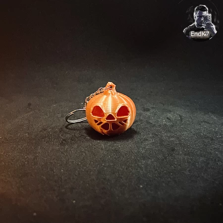
Walking pumpkin ii 3D for print


26733 Views 1 Likes 0 Downloads Download the piece here from 3dforprint
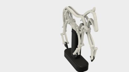
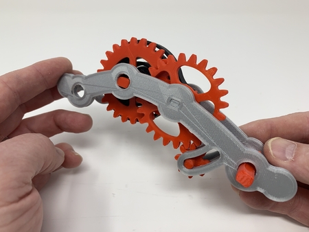
At only 125mm tall and weighing in fully assembled at 93g (32 oz), this version is significantl...y smaller and lighter, and requires fewer parts (both 3D printed and purchased) than the original. A simple rotation of the magnetically attached lid activates a reed switch connecting the battery to the motor that powers our Walking Pumpkin II across our Halloween themed table!
As usual, I probably forgot a file or two or who knows what else, so if you have any questions, please do not hesitate to ask as I do make plenty of mistakes.
Designed using Autodesk Fusion 360, sliced using Cura 4.2, and printed in PLA on an Ultimaker 2+ Extended and an Ultimaker 3 Extended.
One final note, I receive no compensation in any form for the parts and/or materials used in this model.
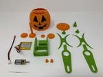
I purchased the following parts:
• 150rpm 6VDC Gear Motor (search online for "DC 6V 150RPM Micro Speed ...Reduction Motor Electric Geared Motor").
• One battery (I've used https://www.adafruit.com/product/1578 and https://www.adafruit.com/product/1570).
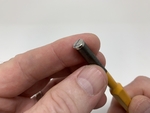
• One JST PH 2-Pin Cable (https://www.adafruit.com/product/3814).
• Four 6.35 by 1.6mm neodymium magnets (local hobby shop).
• Two 12 by 2.7mm neodymium magnets (local hobby shop).
• One reed switch (search online for "Gikfun 20pcs Reed Switch, EK1621x2).
• You will also need a suitable battery charger.
I 3D printed the following parts:
• One "Axle, Drive.stl", 20% infill, .15mm layer height.
• Two "Axle, Leg.stl", 20% infill, .15mm layer height.
• Two "Bolt.stl", 20% infill, .15mm layer height.
• One "Cam, Drive.stl", 20% infill, .15mm layer height.
• One "Chassis.stl", 20% infill, .15mm layer height.
• Two "Foot.stl", 20% infill, .15mm layer height.
• One "Gear, Drive.stl", 20% infill, .15mm layer height.
• One "Gear, Motor.stl", 20% infill, .15mm layer height.
• One "Jack O'Lantern, Lid.stl", 20% infill, .15mm layer height.
• One "Jack O'Lantern.3mf", 20% infill, .15mm layer height.
• Two" Leg.stl", 20% infil", .15mm layer height.
• One "Pin.stl", 20% infill, .15mm layer height.
• One "Stem.stl", 20% infill, .15mm layer height.
This is a high precision print and assembly model. Prior to assembly, test fit and trim, file, sand, etc. all parts as necessary for smooth movement of moving surfaces, and tight fit for non moving surfaces. Depending on you printer, your printer settings and the colors you chose, more or less trimming, filing and/or sanding may be required. Carefully file all edges that contacted the build plate to make absolutely sure that all build plate "ooze" is removed and that all edges are smooth. I used small jewelers files and plenty of patience to perform this step.
I used a tap and die set (6mm by 1) for thread cleaning.
I used small dots of cyanoacrylate glue to secure the wiring to the chassis and to secure threads if needed, and light machine oil for lubrication of the gears and axles.
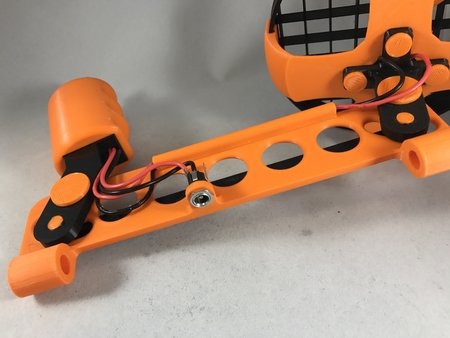
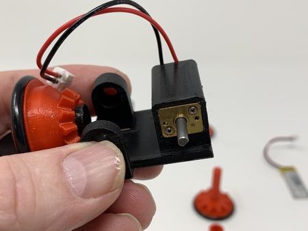
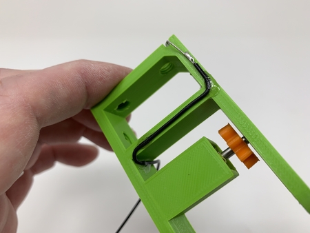
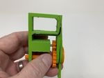
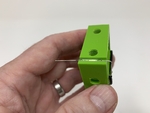
Prepare the Chassis.
To prepare the chassis, I performed the following steps:
• Pressed the motor into the motor mount on "Chassis.stl" leaving about 2mm of the motor shaft exposed (leaving room to install the motor gear).
• Pressed "Gear, Motor.stl" onto the motor shaft.
• Pressed the motor further into the motor mount until the motor was 4mm below the outside side surface of the chassis (providing clearance for the leg).
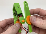
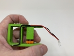
• Soldered a 26awg length of black wire to the motor "-" terminal, routed it to the reed switch slot on the chassis, then secured it in place using thick cyanoacrylate glue.
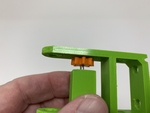
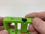
• Placed the reed switch in the chassis assembly then soldered one end of the reed switch to the black wire (leaving enough slack for alignment of the reed switch if required).
• Soldered a 26awg length of black wire to the remaining end of the reed switch, routed it down and through the battery bay on the chassis and out the front, then secured it in place using thick cyanoacrylate glue (again leaving enough slack for alignment of the reed switch if required).
• Soldered the red wire from the JST connector to the motor "+" terminal.
• Soldered the free end of the 26awg black wire to the JST connector black wire.
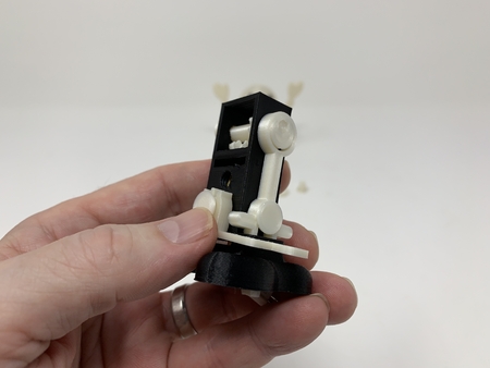
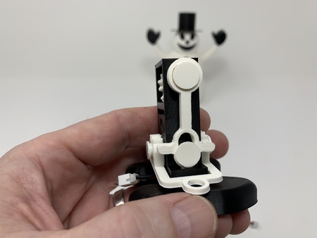
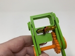
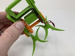
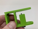
Attach the Legs and Feet.
To attach the legs and feet, I performed the following steps:
• Slid one "Leg.stl" onto "Axle, Drive.stl".
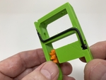
• Slid the drive axle assembly axle partially into the chassis assembly drive axle hole from the motor gear side, pressed "Gear, Drive.stl" onto the drive axle, then slide the axle through the remaining drive axle hole in the chassis.
• Secured the leg assembly to the chassis assembly using one "Axle, Leg.stl".
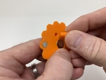
• Placed "Cam, Drive.stl" onto the remaining "Leg.stl" then threaded the assembly onto the drive axle threads such that the cams were 180 degrees from each other (e.g. when one cam was fully up, the remaining cam was fully down).
• Secured the leg assembly to the chassis assembly using the remaining "Axle, Leg.stl".
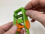
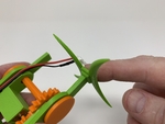
• Pressed one "Foot.stl" onto one of the legs with the longer stems out.
• Pressed the remaining "Foot.stl" onto the remaining leg, again with the longer stems out.
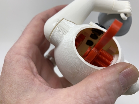
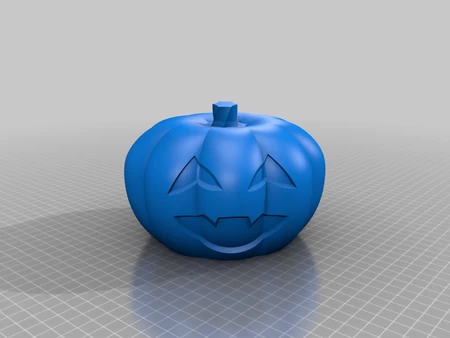
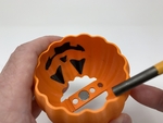
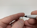
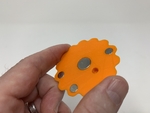
Add the Magnets.
To add the magnets, I performed the following steps:
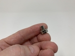
• Stacked the magnets end to end.
• Placed an "X" on the top of the top small magnet.
• Placed the small magnet, with the "X" facing outward, onto a flat punch (any flat surfaced metallic tool would suffice).
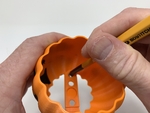
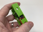
• Pressed the small magnet into the smaller magnet hole in "Jack O'Lantern.3mf".
• Placed an "X" on the top of the top large magnet.
• Placed the large magnet, with the "X" facing outward, onto the flat punch.
• Pressed the large magnet into the larger magnet hole in "Jack O'Lantern.3mf".
• Repeated this process for the remaining three small magnets and one large magnet in "Jack O'Lantern Lid.stl".
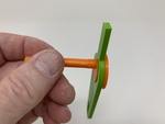
Final Assembly and Operation.
For final assembly, I performed the following steps:
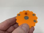
• Threaded "Pin.stl" into the lid assembly.
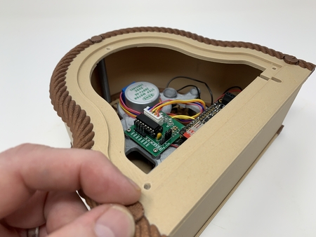
• Secured the battery in the top of the battery bay using double sided tape, making sure the battery and cable will not come in contact with the gears.
• Placed the Jack O'Lantern assembly onto the frame assembly, then secured in place using the two "Bolt.stl".
• Placed the lid onto the Jack O'Lantern assembly.
• Pressed "Stem.stl" onto the lid assembly.
To operate the model, I rotated the lid such that the reed switch magnet (the small isolated magnet in the lid) activates the reed switch. To stop the model, I rotated the lid in the opposite direction. I adjusted the reed switch position if needed.
When the battery depletes, I pull the connectors out of the body, disconnect and charge the battery with a suitable battery charger, then reconnect and tuck the connectors back into the body.
And that is how I 3D printed and assembled "Walking Pumpkin II".
I hope you enjoyed it!
Designer
Greg Zumwalt3d model description
An update of my five year old walking pumpkin design.At only 125mm tall and weighing in fully assembled at 93g (32 oz), this version is significantl...y smaller and lighter, and requires fewer parts (both 3D printed and purchased) than the original. A simple rotation of the magnetically attached lid activates a reed switch connecting the battery to the motor that powers our Walking Pumpkin II across our Halloween themed table!
As usual, I probably forgot a file or two or who knows what else, so if you have any questions, please do not hesitate to ask as I do make plenty of mistakes.
Designed using Autodesk Fusion 360, sliced using Cura 4.2, and printed in PLA on an Ultimaker 2+ Extended and an Ultimaker 3 Extended.
One final note, I receive no compensation in any form for the parts and/or materials used in this model.
3d model print parameters
Purchase, Print and Prepare the Parts.I purchased the following parts:
• 150rpm 6VDC Gear Motor (search online for "DC 6V 150RPM Micro Speed ...Reduction Motor Electric Geared Motor").
• One battery (I've used https://www.adafruit.com/product/1578 and https://www.adafruit.com/product/1570).
• One JST PH 2-Pin Cable (https://www.adafruit.com/product/3814).
• Four 6.35 by 1.6mm neodymium magnets (local hobby shop).
• Two 12 by 2.7mm neodymium magnets (local hobby shop).
• One reed switch (search online for "Gikfun 20pcs Reed Switch, EK1621x2).
• You will also need a suitable battery charger.
I 3D printed the following parts:
• One "Axle, Drive.stl", 20% infill, .15mm layer height.
• Two "Axle, Leg.stl", 20% infill, .15mm layer height.
• Two "Bolt.stl", 20% infill, .15mm layer height.
• One "Cam, Drive.stl", 20% infill, .15mm layer height.
• One "Chassis.stl", 20% infill, .15mm layer height.
• Two "Foot.stl", 20% infill, .15mm layer height.
• One "Gear, Drive.stl", 20% infill, .15mm layer height.
• One "Gear, Motor.stl", 20% infill, .15mm layer height.
• One "Jack O'Lantern, Lid.stl", 20% infill, .15mm layer height.
• One "Jack O'Lantern.3mf", 20% infill, .15mm layer height.
• Two" Leg.stl", 20% infil", .15mm layer height.
• One "Pin.stl", 20% infill, .15mm layer height.
• One "Stem.stl", 20% infill, .15mm layer height.
This is a high precision print and assembly model. Prior to assembly, test fit and trim, file, sand, etc. all parts as necessary for smooth movement of moving surfaces, and tight fit for non moving surfaces. Depending on you printer, your printer settings and the colors you chose, more or less trimming, filing and/or sanding may be required. Carefully file all edges that contacted the build plate to make absolutely sure that all build plate "ooze" is removed and that all edges are smooth. I used small jewelers files and plenty of patience to perform this step.
I used a tap and die set (6mm by 1) for thread cleaning.
I used small dots of cyanoacrylate glue to secure the wiring to the chassis and to secure threads if needed, and light machine oil for lubrication of the gears and axles.
Prepare the Chassis.
To prepare the chassis, I performed the following steps:
• Pressed the motor into the motor mount on "Chassis.stl" leaving about 2mm of the motor shaft exposed (leaving room to install the motor gear).
• Pressed "Gear, Motor.stl" onto the motor shaft.
• Pressed the motor further into the motor mount until the motor was 4mm below the outside side surface of the chassis (providing clearance for the leg).
• Soldered a 26awg length of black wire to the motor "-" terminal, routed it to the reed switch slot on the chassis, then secured it in place using thick cyanoacrylate glue.
• Placed the reed switch in the chassis assembly then soldered one end of the reed switch to the black wire (leaving enough slack for alignment of the reed switch if required).
• Soldered a 26awg length of black wire to the remaining end of the reed switch, routed it down and through the battery bay on the chassis and out the front, then secured it in place using thick cyanoacrylate glue (again leaving enough slack for alignment of the reed switch if required).
• Soldered the red wire from the JST connector to the motor "+" terminal.
• Soldered the free end of the 26awg black wire to the JST connector black wire.
Attach the Legs and Feet.
To attach the legs and feet, I performed the following steps:
• Slid one "Leg.stl" onto "Axle, Drive.stl".
• Slid the drive axle assembly axle partially into the chassis assembly drive axle hole from the motor gear side, pressed "Gear, Drive.stl" onto the drive axle, then slide the axle through the remaining drive axle hole in the chassis.
• Secured the leg assembly to the chassis assembly using one "Axle, Leg.stl".
• Placed "Cam, Drive.stl" onto the remaining "Leg.stl" then threaded the assembly onto the drive axle threads such that the cams were 180 degrees from each other (e.g. when one cam was fully up, the remaining cam was fully down).
• Secured the leg assembly to the chassis assembly using the remaining "Axle, Leg.stl".
• Pressed one "Foot.stl" onto one of the legs with the longer stems out.
• Pressed the remaining "Foot.stl" onto the remaining leg, again with the longer stems out.
Add the Magnets.
To add the magnets, I performed the following steps:
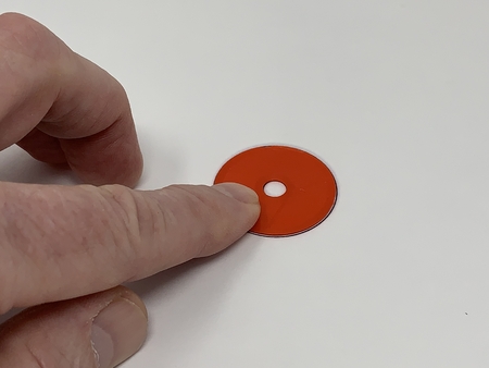
• Stacked the magnets end to end.
• Placed an "X" on the top of the top small magnet.
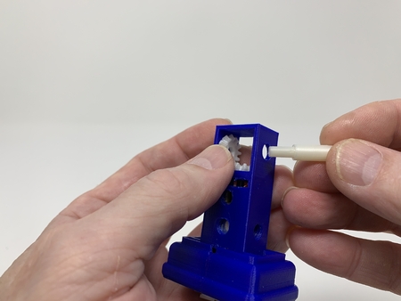
• Placed the small magnet, with the "X" facing outward, onto a flat punch (any flat surfaced metallic tool would suffice).
• Pressed the small magnet into the smaller magnet hole in "Jack O'Lantern.3mf".
• Placed an "X" on the top of the top large magnet.
• Placed the large magnet, with the "X" facing outward, onto the flat punch.
• Pressed the large magnet into the larger magnet hole in "Jack O'Lantern.3mf".
• Repeated this process for the remaining three small magnets and one large magnet in "Jack O'Lantern Lid.stl".
Final Assembly and Operation.
For final assembly, I performed the following steps:
• Threaded "Pin.stl" into the lid assembly.
• Secured the battery in the top of the battery bay using double sided tape, making sure the battery and cable will not come in contact with the gears.
• Placed the Jack O'Lantern assembly onto the frame assembly, then secured in place using the two "Bolt.stl".
• Placed the lid onto the Jack O'Lantern assembly.
• Pressed "Stem.stl" onto the lid assembly.
To operate the model, I rotated the lid such that the reed switch magnet (the small isolated magnet in the lid) activates the reed switch. To stop the model, I rotated the lid in the opposite direction. I adjusted the reed switch position if needed.
When the battery depletes, I pull the connectors out of the body, disconnect and charge the battery with a suitable battery charger, then reconnect and tuck the connectors back into the body.
And that is how I 3D printed and assembled "Walking Pumpkin II".
I hope you enjoyed it!