Fab lab lab tulsa trophy 3d pour imprimer
18349 Vues 1 Goûts 0 Téléchargements Téléchargez ici la pièce à partir de 3dforprint
https://youtu.be/s-barrh3fmm
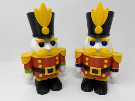
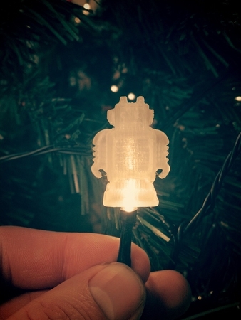
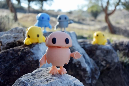
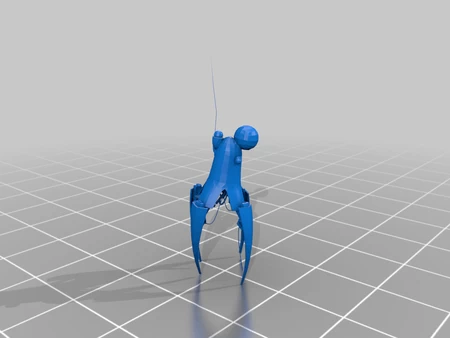
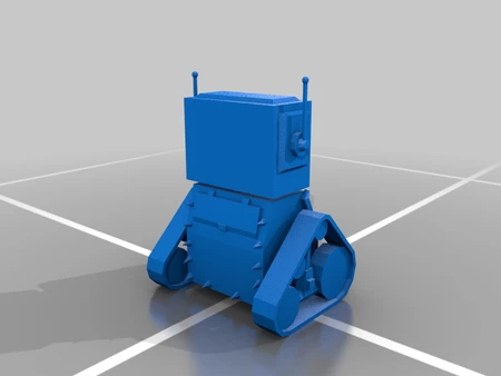
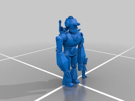
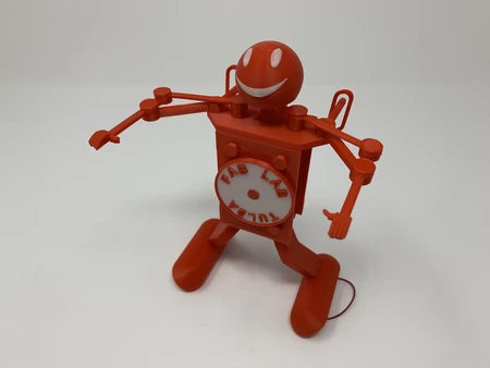
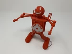
Fab Lab Tulsa a invité notre famille à être leurs invités à Tulsa Maker Faire 2019, e...t bien sûr nous avons accepté avec plaisir. À la fin de notre journée lors de l'événement, nous avons acheté des t-shirts et des robots de «danse» très mignons pour toute la famille. "Fab Lab Tulsa Trophy" est une version motorisée plus grande et moins compliquée des robots de danse Windup que j'ai conçus, imprimés en 3D et assemblés pour remercier Fab Lab Tulsa pour leur hospitalité et pour célébrer leur succès avec Tulsa Maker Faire 2019.
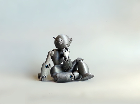
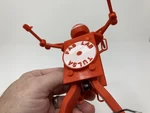
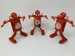
Avec le premier trophée terminé, tous ceux qui l'ont vu souri. J'ai donc mis à jour la conception de la famille et des amis pour inclure des fronts de vitesse animés et des médaillons personnalisés / personnalisables. J'ai inclus le fichier "Medallion, Blank.stl" auquel un autocollant imprimé 2D peut être appliqué pour personnaliser le trophée.
Comme d'habitude, j'ai probablement oublié un fichier ou deux ou qui sait quoi d'autre, donc si vous avez des questions, n'hésitez pas à demander car je fais beaucoup d'erreurs.
Conçu à l'aide d'Autodesk Fusion 360, tranché à l'aide de Cura 4.2, et imprimé dans PLA sur un ultimaker 2+ étendu et un ultimaker 3 étendu.
J'ai acheté les parties suivantes:
• Motor d'engrenage 6VDC 150 tr / min (Recherchez "DC 6V 150 tr / ...min Motor de réduction de vitesse Motor électrique à engrenages").
• Un adaptateur d'alimentation variable de 1,5, 3, 4,5, 5VDC (disponible en ligne).
Le fichier inclus "Parts.pdf" contient les noms de pièce, les quantités, les hauteurs de la couche, les paramètres de remplissage et de support des pièces I 3D imprimées pour ce modèle. Le fichier "Medallion, Blank.stl" contient un médaillon vide auquel un autocollant imprimé 2D peut être appliqué pour la personnalisation. Les fichiers ".3mf" sont destinés à la tête et aux médaillons à double extrusion.
Il s'agit d'un modèle d'impression et d'assemblage de haute précision. Avant l'assemblage, le test d'ajustement et de garniture, le fichier, le sable, etc. toutes les pièces nécessaires pour le mouvement lisse des surfaces mobiles et l'ajustement serré pour les surfaces non mobiles. Selon votre imprimante, les paramètres de votre imprimante et les couleurs que vous avez choisis, plus ou moins la coupe, le dépôt et / ou le ponçage peuvent être nécessaires. Déposer soigneusement tous les bords qui ont contacté la plaque de construction pour s'assurer que toutes les plaques de construction "suinter" sont supprimées et que tous les bords sont lisses. J'ai utilisé de petits fichiers de bijoutiers et beaucoup de patience pour effectuer cette étape.
Le modèle utilise également un assemblage fileté, j'ai donc utilisé un jeu de robinet et de matrice (6 mm par 1, 8 mm par 1,25) pour le nettoyage des filetages.
J'ai utilisé de petits points de colle cyanoacrylate pour sécuriser les fils si nécessaire, et l'huile de machine légère pour la lubrification des engrenages et des essieux.
Assemblez le corps.
Pour assembler le corps, j'ai effectué les étapes suivantes:
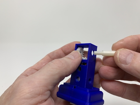
• Appuyez sur le moteur dans "corps, arrière.stl" jusqu'à ce que l'arbre du moteur s'étende à 3 mm au-dessus de la plaque d'engrenage du moteur.
• Longueurs soudées de 120 mm de fils rouges et noirs aux bornes "et" - "respectivement" et "-" respectivement, puis a utilisé un petit point de colle cyanoacrylate épaisse pour fixer les fils au corps pour un soulagement de la déformation.
• pressé "cou.stl" dans l'assemblage du corps.
• Appuyez sur "Gear, Crown, Motor.stl" sur l'arbre du moteur.
• Positionné "Gear, couronne, essieu.stl" sur l'assemblage du corps, appuyé sur "essieu, cam.stl" à travers l'équipement de la couronne et l'arrière de l'assemblage du corps, puis fileté "cam.stl" sur l'essieu trop serré.
• Positionné "corps, avant.stl" sur l'assemblage du corps et fixé en place avec deux "boulon, front.stl".
Assemblez et fixez les jambes.
Pour assembler et fixer les jambes, j'ai effectué les étapes suivantes:
• Fiffé un "broche, leg.stl" dans "jambe, gauche.stl".
• Filé les fils du moteur dans l'ensemble de la jambe gauche et sortir à travers le pied.
• Attaché l'assemblage de la jambe gauche à l'ensemble du corps à l'aide d'un "essieu, jambe, jambe" "en s'assurant de ne pas trop tendre l'essieu.
• Fillé le reste "Pin, leg.stl" en "jambe, à droite.stl".
• Attaché l'assemblage de la jambe droite à l'assemblage du corps à l'aide d'un "essieu, jambe, jambe" "s'assurer de ne pas trop tendre l'essieu.
• Assurez-vous que les deux ensembles de jambes tournaient facilement.
Assemblez et attachez les bras.
Pour assembler et fixer les bras, j'ai effectué les étapes suivantes:
• Positionné "bras, gauche, inférieur.stl" Over "bras, gauche, supérieur.stl" et fixé en place à l'aide d'un "boulon, arms.stl", en s'assurant de ne pas trop serrer le boulon.
• Positionné "bras, swing.stl" sur l'assemblage du bras et fixé en place à l'aide d'un "boulon, arms.stl", en s'assurant de ne pas trop serrer le boulon.
• Attaché l'extrémité libre du swing du bras au corps en utilisant un "boulon, épaule, long.stl", en s'assurant de ne pas trop serrer le boulon.
• Attaché l'extrémité libre du bras supérieur au corps à l'aide d'un "boulon, épaule, court.stl", en s'assurant de ne pas trop serrer le boulon.
• Répété ces étapes pour le bras droit.
• Assurez-vous que les deux ensembles de bras tournaient facilement.
Fixez la tête.
Pour attacher la tête, j'ai effectué les étapes suivantes:
• Appuyé sur "bras, tête.stl" sur "essieu, cou.stl".
• Positionnée "tête de 3 mf" sur le cou, puis a enfilé l'essieu à travers la tête et le cou jusqu'à ce qu'il soit bien ajusté et le bras est positionné directement vers le bas.
• Assurez-vous que l'ensemble de tête tournait librement.
Assemblage final.
Pour l'assemblage final, j'ai effectué les étapes suivantes:
• Position de "plaque de commande" positionnée sur l'assemblage du corps de telle sorte que les deux broches du bras, les deux épingles de jambe et la broche de tête étaient situées dans les fentes de plaque de commande.
• Fiffée "essieu, plaque de commande.stl" à travers le trou dans la plaque de commande et dans l'assemblage du corps, en s'assurant de ne pas trop serrer l'essieu et que l'essieu tournait librement.
• Fiffée "essieu, cam.stl" à travers la fente dans la plaque de commande et dans la came, en s'assurant de ne pas trop serrer l'essieu.
• Filé le médaillon sur l'essieu de la came, en s'assurant de ne pas trop serrer le médaillon.
• Souder les fils de l'adaptateur d'alimentation aux fils du moteur rouge et noir, puis a fixé la longueur supplémentaire du fil à l'intérieur du pied gauche à l'aide de petits points de colle cyanoacrylate.
Avec un assemblage final complet, j'ai placé de petits points d'huile de machine légère sur les engrenages et les essieux, réglé l'alimentation sur 1,5 VDC et l'ai branché. À l'aide d'un ampèreter, j'ai mesuré le tirage au courant de chaque modèle et je l'ai trouvé entre 12 et 20mA.
Et c'est ainsi que j'ai imprimé 3D imprimé et assemblé le trophée Fab Lab Tulsa.
J'espère que vous l'avez apprécié!
Designer
Greg ZumwaltDescription du modèle 3D
Un trophée pour Fab Lab Tulsahttps://youtu.be/s-barrh3fmm
Fab Lab Tulsa a invité notre famille à être leurs invités à Tulsa Maker Faire 2019, e...t bien sûr nous avons accepté avec plaisir. À la fin de notre journée lors de l'événement, nous avons acheté des t-shirts et des robots de «danse» très mignons pour toute la famille. "Fab Lab Tulsa Trophy" est une version motorisée plus grande et moins compliquée des robots de danse Windup que j'ai conçus, imprimés en 3D et assemblés pour remercier Fab Lab Tulsa pour leur hospitalité et pour célébrer leur succès avec Tulsa Maker Faire 2019.
Avec le premier trophée terminé, tous ceux qui l'ont vu souri. J'ai donc mis à jour la conception de la famille et des amis pour inclure des fronts de vitesse animés et des médaillons personnalisés / personnalisables. J'ai inclus le fichier "Medallion, Blank.stl" auquel un autocollant imprimé 2D peut être appliqué pour personnaliser le trophée.
Comme d'habitude, j'ai probablement oublié un fichier ou deux ou qui sait quoi d'autre, donc si vous avez des questions, n'hésitez pas à demander car je fais beaucoup d'erreurs.
Conçu à l'aide d'Autodesk Fusion 360, tranché à l'aide de Cura 4.2, et imprimé dans PLA sur un ultimaker 2+ étendu et un ultimaker 3 étendu.
Paramètres d'impression du modèle 3D
Achetez, imprimez et préparez les pièces.J'ai acheté les parties suivantes:
• Motor d'engrenage 6VDC 150 tr / min (Recherchez "DC 6V 150 tr / ...min Motor de réduction de vitesse Motor électrique à engrenages").
• Un adaptateur d'alimentation variable de 1,5, 3, 4,5, 5VDC (disponible en ligne).
Le fichier inclus "Parts.pdf" contient les noms de pièce, les quantités, les hauteurs de la couche, les paramètres de remplissage et de support des pièces I 3D imprimées pour ce modèle. Le fichier "Medallion, Blank.stl" contient un médaillon vide auquel un autocollant imprimé 2D peut être appliqué pour la personnalisation. Les fichiers ".3mf" sont destinés à la tête et aux médaillons à double extrusion.
Il s'agit d'un modèle d'impression et d'assemblage de haute précision. Avant l'assemblage, le test d'ajustement et de garniture, le fichier, le sable, etc. toutes les pièces nécessaires pour le mouvement lisse des surfaces mobiles et l'ajustement serré pour les surfaces non mobiles. Selon votre imprimante, les paramètres de votre imprimante et les couleurs que vous avez choisis, plus ou moins la coupe, le dépôt et / ou le ponçage peuvent être nécessaires. Déposer soigneusement tous les bords qui ont contacté la plaque de construction pour s'assurer que toutes les plaques de construction "suinter" sont supprimées et que tous les bords sont lisses. J'ai utilisé de petits fichiers de bijoutiers et beaucoup de patience pour effectuer cette étape.
Le modèle utilise également un assemblage fileté, j'ai donc utilisé un jeu de robinet et de matrice (6 mm par 1, 8 mm par 1,25) pour le nettoyage des filetages.
J'ai utilisé de petits points de colle cyanoacrylate pour sécuriser les fils si nécessaire, et l'huile de machine légère pour la lubrification des engrenages et des essieux.
Assemblez le corps.
Pour assembler le corps, j'ai effectué les étapes suivantes:
• Appuyez sur le moteur dans "corps, arrière.stl" jusqu'à ce que l'arbre du moteur s'étende à 3 mm au-dessus de la plaque d'engrenage du moteur.
• Longueurs soudées de 120 mm de fils rouges et noirs aux bornes "et" - "respectivement" et "-" respectivement, puis a utilisé un petit point de colle cyanoacrylate épaisse pour fixer les fils au corps pour un soulagement de la déformation.
• pressé "cou.stl" dans l'assemblage du corps.
• Appuyez sur "Gear, Crown, Motor.stl" sur l'arbre du moteur.
• Positionné "Gear, couronne, essieu.stl" sur l'assemblage du corps, appuyé sur "essieu, cam.stl" à travers l'équipement de la couronne et l'arrière de l'assemblage du corps, puis fileté "cam.stl" sur l'essieu trop serré.
• Positionné "corps, avant.stl" sur l'assemblage du corps et fixé en place avec deux "boulon, front.stl".
Assemblez et fixez les jambes.
Pour assembler et fixer les jambes, j'ai effectué les étapes suivantes:
• Fiffé un "broche, leg.stl" dans "jambe, gauche.stl".
• Filé les fils du moteur dans l'ensemble de la jambe gauche et sortir à travers le pied.
• Attaché l'assemblage de la jambe gauche à l'ensemble du corps à l'aide d'un "essieu, jambe, jambe" "en s'assurant de ne pas trop tendre l'essieu.
• Fillé le reste "Pin, leg.stl" en "jambe, à droite.stl".
• Attaché l'assemblage de la jambe droite à l'assemblage du corps à l'aide d'un "essieu, jambe, jambe" "s'assurer de ne pas trop tendre l'essieu.
• Assurez-vous que les deux ensembles de jambes tournaient facilement.
Assemblez et attachez les bras.
Pour assembler et fixer les bras, j'ai effectué les étapes suivantes:
• Positionné "bras, gauche, inférieur.stl" Over "bras, gauche, supérieur.stl" et fixé en place à l'aide d'un "boulon, arms.stl", en s'assurant de ne pas trop serrer le boulon.
• Positionné "bras, swing.stl" sur l'assemblage du bras et fixé en place à l'aide d'un "boulon, arms.stl", en s'assurant de ne pas trop serrer le boulon.
• Attaché l'extrémité libre du swing du bras au corps en utilisant un "boulon, épaule, long.stl", en s'assurant de ne pas trop serrer le boulon.
• Attaché l'extrémité libre du bras supérieur au corps à l'aide d'un "boulon, épaule, court.stl", en s'assurant de ne pas trop serrer le boulon.
• Répété ces étapes pour le bras droit.
• Assurez-vous que les deux ensembles de bras tournaient facilement.
Fixez la tête.
Pour attacher la tête, j'ai effectué les étapes suivantes:
• Appuyé sur "bras, tête.stl" sur "essieu, cou.stl".
• Positionnée "tête de 3 mf" sur le cou, puis a enfilé l'essieu à travers la tête et le cou jusqu'à ce qu'il soit bien ajusté et le bras est positionné directement vers le bas.
• Assurez-vous que l'ensemble de tête tournait librement.
Assemblage final.
Pour l'assemblage final, j'ai effectué les étapes suivantes:
• Position de "plaque de commande" positionnée sur l'assemblage du corps de telle sorte que les deux broches du bras, les deux épingles de jambe et la broche de tête étaient situées dans les fentes de plaque de commande.
• Fiffée "essieu, plaque de commande.stl" à travers le trou dans la plaque de commande et dans l'assemblage du corps, en s'assurant de ne pas trop serrer l'essieu et que l'essieu tournait librement.
• Fiffée "essieu, cam.stl" à travers la fente dans la plaque de commande et dans la came, en s'assurant de ne pas trop serrer l'essieu.
• Filé le médaillon sur l'essieu de la came, en s'assurant de ne pas trop serrer le médaillon.
• Souder les fils de l'adaptateur d'alimentation aux fils du moteur rouge et noir, puis a fixé la longueur supplémentaire du fil à l'intérieur du pied gauche à l'aide de petits points de colle cyanoacrylate.
Avec un assemblage final complet, j'ai placé de petits points d'huile de machine légère sur les engrenages et les essieux, réglé l'alimentation sur 1,5 VDC et l'ai branché. À l'aide d'un ampèreter, j'ai mesuré le tirage au courant de chaque modèle et je l'ai trouvé entre 12 et 20mA.
Et c'est ainsi que j'ai imprimé 3D imprimé et assemblé le trophée Fab Lab Tulsa.
J'espère que vous l'avez apprécié!