Libre hardware licensed parametric laptop design 3D for print

5170 Views 2 Likes 0 Downloads Download the piece here from 3dforprint
PLEASE NOTE: YOUMAGINE STILL HAVE NOT RESPONDED TO REQUESTS TO ADD GPLv3+ TO THE LIST OF LICENSES IN THE DROP-DOWN MENU FOR REGISTERING PROJECTS ON THIS SITE. THE FILES FOR THIS PROJECT ARE SPECIFICALLY LICENSED UNDER THE GPLv3+ NOT THE GPLv3. SITE ADMINS I HAVE ASKED YOU TO ADD THIS OPTION ALREADY. YES IT REALLY MATTERS. YES IT IS A DIFFERENT LICENSE.
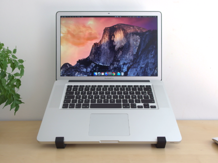
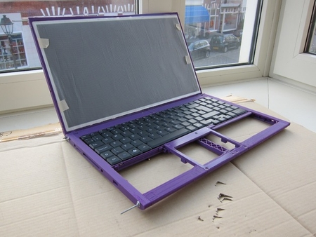
This is a Libre Hardware (GPLv3+) Licensed Parametric Laptop Design which may be adjusted to create anything from an 8in laptop to a 15.6in laptop.
News and progress: http://rhombus-tech.net/community_ideas/laptop_15in/news/
Sign-ups for the crowd-funding when the product this is going into is released: https://www.crowdsupply.com/eoma68/
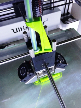
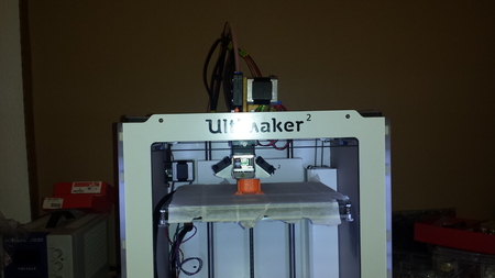
The parts are deliberately designed to be printable on a standard 200x200mm Mendel90 style 3D printer, so that even a 15.6in laptop may be created by printing the longest parts (260mm) across the diagonal of a Mendel90 print bed (280mm). Individual parts are no more than 1,000mm of 3mm PLA, meaning that a single part incorrectly printed does not lose the entire prior printed work.
Assembly involves M2.5 bolts, M2 8mm screws and M3 bolts, and the central areas are designed to be filled in with bamboo laminates, to save materials and 3D printing. The M2 bolts in the prototype are currently made from M2 threaded bar (cut by hand). The hinges required two M3 bolts (25 to 30mm) because not enough friction could be generated with M2 bolts.
Printing the parts has proven... tricky. The case thickness is set to only 1.2mm, and there are long (and thin) parts with internal holes with very thin walls being printed as the first layer which come unstuck (even from a heated bed) and curl up either instantly or worse after a few layers have been printed. Solving this problem involved adding small squares 0.6mm high at critical points (corners etc.) which can be trimmed or broken off once the print is complete.
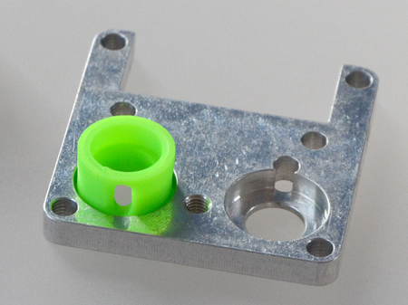
The parts are also designed with adaptation to injection molding, where the mold parts will be parametrically generated from the exact same source code, then DLP 3D-printed as LostResin parts and flash-cast to metal.
Source files are available here: http://hands.com/~lkcl/eoma/kde_tablet/3dcase/ and may be checked out with git clone http://hands.com/~lkcl/eoma/kde_tablet/3dcase/.git/ The source code is in python (pyopenscad) and auto-generates (very large) openscad files (anyone who would like help making this should join the arm-netbooks mailing list http://lists.phcomp.co.uk/mailman/listinfo/arm-netbook).
A modified version of pyopenscad is included, as is an upgraded version of pyopenspline, and a utility python file including a function that can be used to create hollow boxes with curved corners (including elliptical shaped corners). hollowbox is distinctly a work-in-progress but is sufficient for the purpose being used for, here.
Instructions:
* install git, python 2 and openscad
* clone the git repository with the command git clone http://hands.com/~lkcl/eoma/kde_tablet/3dcase/.git/
* edit the file laptop_model2.py and repeat-search for the word BASE_END
* when encountering a list containing all parts, uncomment one (and only one) of the items to be printed (remove the #, ensure that all others have a #).
* go back to the beginning of the file and set the variable "mirroring" to either LEFTPART or RIGHTPART as in "mirroring = LEFTPART".
* also ensure that "pin_parts_3d = True", "test = False", "cutdown = False" and "add_internal_parts = False".
* save the file then in another window run the command "python laptop_model2.py". this may take a few seconds if the part is large.
* run openscad and open the auto-generated file "laptop_model2.scad".
* press F6 to compile-and-render the part. this may take several minutes. do not be tempted to terminate openscad: it's just doing its job (very slowly).
* when the part finally shows up in green and yellow, go to "File | Export" and save the result as an STL file.
* transfer the STL file to a preferred 3D printer slicer program if using a 200x200mm bed (mendel90 for example) some parts will require 45 degree rotation in order to fit across the diagonal. no parts are larger than sqrt(2)200mm: they *will fit.
* ensure also that the part is orientated so that the "pinning" squares are at the bottom layer! bear in mind also that if you use auto-place it may get things wrong, particularly in instances where the (prototype) function hollowbox has an accidental protrusion that is not flush with the rest of the part.
* when slicing use a layer height of 0.2mm (or less if you prefer, and are happy to experiment) because some of the parts are quite thin. if you use a layer height of 0.3mm, chances are that some of the walls and some of the detail will be destroyed (as either entirely blank or as a single wall). fill-in of only 15% has proven successful, as most of the strength is in cross-struts and curves that are only 0.8 to 1mm thick.
* BASE_BACK can take well over an hour to print. it is only 12mm wide, but is 30mm high and over 160mm long. it is recommended that this part in particular is transferred to a MicroSD card (on a mendel90) rather than printed over the USB-UART. it can be extremely annoying to have the part get 90% of the way through its 3 metres of PLA and just... stop.
* once each part is done go back and hand-edit laptop_model2.py and do the next part. CASE_CLASP, CLASP_NIB and FRICTION_HINGE2 do not need to be printed.
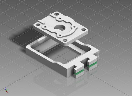
in theory PCB1 and/or PCB2 could be 3D-printed (for dummy / demo purposes) but they are actually there as a guide for the design of the real PCBs.
assembly is, to be absolutely honest and frank, a pain in the neck, as the parts have sufficient detail (as well as requiring "pinning") that they need quite a lot of post-print scalpel work. perhaps other people with much more expensive and professional-grade printers than a mendel90 will have better luck and will require less trimming of the parts. printing with a DLP would be a lot easier!
the main reason found for the "pinning" (on a mendel90) is because the parts are quite long and thin. BASE_BACK for example has a first layer where the top and bottom edges are only 1mm thick... but are 160mm long... and there's an air gap of 10mm between them! filling this entire air-gap with a single 0.2mm layer (which can be removed after printing) was found to be the only way to get this complex part to stick to the damn print-bed for the 60+ minute duration.
BASE_MID in particular is unusual as it needs to be printed "against the curve". enabling "pinning" provides suitable under-curve support structures that will need to be cut then filed away. all other pieces with large curves are either printed on their sides, or the curves are small enough that underside mid-air support is not needed.
Tools needed:
* phillips screwdriver
* x-acto or other really sharp and small craft knife
* pincer-nosed pliers or if you want to get fancy actual spanners for the M2 and M3 nuts.
* something that will do as a hammer (for example... a hammer!)
* key file(s)
* 1.5mm jeweller's screwdriver (or other suitable very thin tool for digging into holes that need clearing of inaccurately-printed debris)
the hand-made M2 bolts (of varying lengths) will later be substituted with correct-length M2 phillips head bolts that will fit into the chamfered recessed holes, obviating the need for any washers, but for now the hand-made M2 bolts stick out, and the washers are there to ensure that the nuts do not disappear into the chamfered recessed holes.
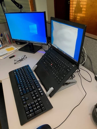
if you'd actually like to put the kayboard and LCD in, you'll need Quanta P/N AEPE1E00010 (or Chicony P/N MP-03756GB-9206) or similar, and for the LCD you will need AUO P/N B156XTN02.2 or equivalent (it's the same LCD, re-branded).
some of the parts have a recess for the M2 nuts. these parts are SCREEN_BACK_EDGE, SCREEN_FRONT_EDGE, BASE_BACK and BASE_FRONT_TOP. BASE_BACK's recess is quite high up so has had some "pinning" put in which can, if desired, be removed with the pliers. the M2 nut recesses almost certainly will require cleaning out BEFORE putting the nut in. the nut recesses are designed so that the nut goes in straight, without rotating. if it rotates (so that a flat surface is facing towards you instead of the join between two flat surfaces) then it's all gone horribly wrong and you should, with suitable tools, endeavour to poke the damn nut to get it to rotate by 30 degrees. it really is important to ensure that the nut recess is properly clear: once it is, the threads of the nut will be clearly seen through the bolt hole at the end of each part. before assembling check that the threaded bar will go into the nut, both before inserting the nut into the recess as well as after. make sure that the bar goes in straight! if the nut is ruined or not in place properly, it is often impossible to get it back out and the part will need to be thrown away.
when tightening up the threaded bar, do not overtighten! the LCD parts in particular do not need a lot of force, but for the BASE_END a surprisingly large amount of force can (and does) need to be applied. the washers should actually end up bending slightly. M2 bar is not hugely strong, so do not overstrip the threads nor tighten so hard that the interlocking between the BASE_END and the back and front parts begins to bow or even crack! use common sense, here, make sure that the parts fit neatly together (clear them carefully with the x-acto knife) but once assembled there should be no creaking or play (at all) - the BASE parts all have double-interlock, even where the LCD cable threads through the middle of BASE_BACK and BASE_END.
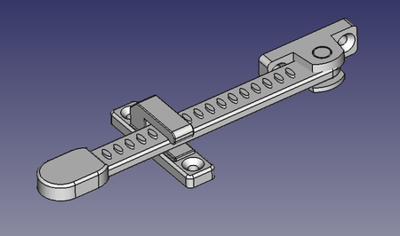
assembly of the friction hinge is a matter of inserting the M3 bolt into SCREEN_HINGE: under no circumstances tighten the M3 bolt down without having a locking nut on the other side. screw in the M3 bolt until it begins to resist slightly, then hand-tighten the nut against the other side. then, work patiently to alternately tighten the nut and the bolt, ensuring that there is no gap between the nut head and the plastic. if the bolt is tightened with a screwdriver without the nut on the other side chances are that SCREEN_HINGE will simply crack.
once the bolt is firmly (really firmly) in place, lock down another two nuts (really firmly but without stripping the M3 thread), then drop on three M3 washers, screw on FRICTION_HINGE2, then drop on another three washers and lock it down with two more nuts. FRICTION_HINGE2 should require holding with pliers to make it turn, but it should actually turn... just about. it should certainly not be loose: it should not be so hard to turn that the SCREEN_HINGE hurts your fingers when holding it. getting the exact torque though will require some experimentation. it is best to err on the side of caution first. remember to take care not to lock the nuts down so tight as to strip the thread on the M3 bolt.
also, when putting FRICTION_HINGE2+SCREEN_HINGE into the hinge hole on BASE_BACK, it should go in cleanly without a huge amount of pressure. exerting too much force will simply crack the BASE_BACK hinge hole. the hole may need cleaning out properly with a round file (6 to 7mm diameter is best but anything will do). also make sure that the locking channel is clear: it tapers inwards so that the nib on FRICTION_HINGE2 locks into place. bear in mind that there is a stop-plate at the end of the hinge hole, and that there are cut-outs in the internal support structures so that slightly longer bolts (up to around 35mm) may be accommodated.
use common sense and patience when working out the assembly order of the parts: it is quite specific. don't screw both sides of the LCD on before inserting the two friction hinge parts into BASE_BACK left / right, for example. TPANEL_MID should be screwed to BASE_FRONT_TOP left / right before being attached to any other parts (especially BASE_MID). BASE_MID should be attached to BASE_BACK left / right as a separate assembly. and so on and so forth.
also note, if ever you wish to see in 3D (OpenSCAD) what the parts look like, assembled together, simply uncomment more of the list of parts and re-generate. be warned: enabling even 25% of the parts simultaneously will require enormous CPU resources, even with OpenGL hardware acceleration. setting "test = True" can help, here, as the parts are shrunk to an alternative (7in) laptop size that was useful during early development, especially of the corner (join) areas. "add_internal_parts = True" is very useful to show a 3D rendition of the keyboard, screen and other components.
any questions and success stories should be directed to the mailing list http://lists.phcomp.co.uk/mailman/listinfo/arm-netbook. success stories especially appreciated.
* QTY 8of 5mm M2.5 screws (for the LCD).
* QTY 2of 25mm M3 bolts (phillips head, head diameter a maximum of 6m...m)
* QTY 12of M3 washers
* QTY 2of M3 locking-washers
* QTY 10of M3 nuts
* QTY 2of 35mm M2.5 bolts
* QTY 2of M2.5 nuts
Designer
lkcl3d model description
This is a Libre Hardware (GPLv3+) Licensed Parametric Laptop Design which may be adjusted to create anything from an 8in laptop to a 15.6in laptop. Ne...ws and progress: http://rhombus-tech.net/community_ideas/laptop_15in/news/PLEASE NOTE: YOUMAGINE STILL HAVE NOT RESPONDED TO REQUESTS TO ADD GPLv3+ TO THE LIST OF LICENSES IN THE DROP-DOWN MENU FOR REGISTERING PROJECTS ON THIS SITE. THE FILES FOR THIS PROJECT ARE SPECIFICALLY LICENSED UNDER THE GPLv3+ NOT THE GPLv3. SITE ADMINS I HAVE ASKED YOU TO ADD THIS OPTION ALREADY. YES IT REALLY MATTERS. YES IT IS A DIFFERENT LICENSE.
This is a Libre Hardware (GPLv3+) Licensed Parametric Laptop Design which may be adjusted to create anything from an 8in laptop to a 15.6in laptop.
News and progress: http://rhombus-tech.net/community_ideas/laptop_15in/news/
Sign-ups for the crowd-funding when the product this is going into is released: https://www.crowdsupply.com/eoma68/
The parts are deliberately designed to be printable on a standard 200x200mm Mendel90 style 3D printer, so that even a 15.6in laptop may be created by printing the longest parts (260mm) across the diagonal of a Mendel90 print bed (280mm). Individual parts are no more than 1,000mm of 3mm PLA, meaning that a single part incorrectly printed does not lose the entire prior printed work.
Assembly involves M2.5 bolts, M2 8mm screws and M3 bolts, and the central areas are designed to be filled in with bamboo laminates, to save materials and 3D printing. The M2 bolts in the prototype are currently made from M2 threaded bar (cut by hand). The hinges required two M3 bolts (25 to 30mm) because not enough friction could be generated with M2 bolts.
Printing the parts has proven... tricky. The case thickness is set to only 1.2mm, and there are long (and thin) parts with internal holes with very thin walls being printed as the first layer which come unstuck (even from a heated bed) and curl up either instantly or worse after a few layers have been printed. Solving this problem involved adding small squares 0.6mm high at critical points (corners etc.) which can be trimmed or broken off once the print is complete.
The parts are also designed with adaptation to injection molding, where the mold parts will be parametrically generated from the exact same source code, then DLP 3D-printed as LostResin parts and flash-cast to metal.
Source files are available here: http://hands.com/~lkcl/eoma/kde_tablet/3dcase/ and may be checked out with git clone http://hands.com/~lkcl/eoma/kde_tablet/3dcase/.git/ The source code is in python (pyopenscad) and auto-generates (very large) openscad files (anyone who would like help making this should join the arm-netbooks mailing list http://lists.phcomp.co.uk/mailman/listinfo/arm-netbook).
A modified version of pyopenscad is included, as is an upgraded version of pyopenspline, and a utility python file including a function that can be used to create hollow boxes with curved corners (including elliptical shaped corners). hollowbox is distinctly a work-in-progress but is sufficient for the purpose being used for, here.
Instructions:
* install git, python 2 and openscad
* clone the git repository with the command git clone http://hands.com/~lkcl/eoma/kde_tablet/3dcase/.git/
* edit the file laptop_model2.py and repeat-search for the word BASE_END
* when encountering a list containing all parts, uncomment one (and only one) of the items to be printed (remove the #, ensure that all others have a #).
* go back to the beginning of the file and set the variable "mirroring" to either LEFTPART or RIGHTPART as in "mirroring = LEFTPART".
* also ensure that "pin_parts_3d = True", "test = False", "cutdown = False" and "add_internal_parts = False".
* save the file then in another window run the command "python laptop_model2.py". this may take a few seconds if the part is large.
* run openscad and open the auto-generated file "laptop_model2.scad".
* press F6 to compile-and-render the part. this may take several minutes. do not be tempted to terminate openscad: it's just doing its job (very slowly).
* when the part finally shows up in green and yellow, go to "File | Export" and save the result as an STL file.
* transfer the STL file to a preferred 3D printer slicer program if using a 200x200mm bed (mendel90 for example) some parts will require 45 degree rotation in order to fit across the diagonal. no parts are larger than sqrt(2)200mm: they *will fit.
* ensure also that the part is orientated so that the "pinning" squares are at the bottom layer! bear in mind also that if you use auto-place it may get things wrong, particularly in instances where the (prototype) function hollowbox has an accidental protrusion that is not flush with the rest of the part.
* when slicing use a layer height of 0.2mm (or less if you prefer, and are happy to experiment) because some of the parts are quite thin. if you use a layer height of 0.3mm, chances are that some of the walls and some of the detail will be destroyed (as either entirely blank or as a single wall). fill-in of only 15% has proven successful, as most of the strength is in cross-struts and curves that are only 0.8 to 1mm thick.
* BASE_BACK can take well over an hour to print. it is only 12mm wide, but is 30mm high and over 160mm long. it is recommended that this part in particular is transferred to a MicroSD card (on a mendel90) rather than printed over the USB-UART. it can be extremely annoying to have the part get 90% of the way through its 3 metres of PLA and just... stop.
* once each part is done go back and hand-edit laptop_model2.py and do the next part. CASE_CLASP, CLASP_NIB and FRICTION_HINGE2 do not need to be printed.
in theory PCB1 and/or PCB2 could be 3D-printed (for dummy / demo purposes) but they are actually there as a guide for the design of the real PCBs.
assembly is, to be absolutely honest and frank, a pain in the neck, as the parts have sufficient detail (as well as requiring "pinning") that they need quite a lot of post-print scalpel work. perhaps other people with much more expensive and professional-grade printers than a mendel90 will have better luck and will require less trimming of the parts. printing with a DLP would be a lot easier!
the main reason found for the "pinning" (on a mendel90) is because the parts are quite long and thin. BASE_BACK for example has a first layer where the top and bottom edges are only 1mm thick... but are 160mm long... and there's an air gap of 10mm between them! filling this entire air-gap with a single 0.2mm layer (which can be removed after printing) was found to be the only way to get this complex part to stick to the damn print-bed for the 60+ minute duration.
BASE_MID in particular is unusual as it needs to be printed "against the curve". enabling "pinning" provides suitable under-curve support structures that will need to be cut then filed away. all other pieces with large curves are either printed on their sides, or the curves are small enough that underside mid-air support is not needed.
Tools needed:
* phillips screwdriver
* x-acto or other really sharp and small craft knife
* pincer-nosed pliers or if you want to get fancy actual spanners for the M2 and M3 nuts.
* something that will do as a hammer (for example... a hammer!)
* key file(s)
* 1.5mm jeweller's screwdriver (or other suitable very thin tool for digging into holes that need clearing of inaccurately-printed debris)
the hand-made M2 bolts (of varying lengths) will later be substituted with correct-length M2 phillips head bolts that will fit into the chamfered recessed holes, obviating the need for any washers, but for now the hand-made M2 bolts stick out, and the washers are there to ensure that the nuts do not disappear into the chamfered recessed holes.
if you'd actually like to put the kayboard and LCD in, you'll need Quanta P/N AEPE1E00010 (or Chicony P/N MP-03756GB-9206) or similar, and for the LCD you will need AUO P/N B156XTN02.2 or equivalent (it's the same LCD, re-branded).
some of the parts have a recess for the M2 nuts. these parts are SCREEN_BACK_EDGE, SCREEN_FRONT_EDGE, BASE_BACK and BASE_FRONT_TOP. BASE_BACK's recess is quite high up so has had some "pinning" put in which can, if desired, be removed with the pliers. the M2 nut recesses almost certainly will require cleaning out BEFORE putting the nut in. the nut recesses are designed so that the nut goes in straight, without rotating. if it rotates (so that a flat surface is facing towards you instead of the join between two flat surfaces) then it's all gone horribly wrong and you should, with suitable tools, endeavour to poke the damn nut to get it to rotate by 30 degrees. it really is important to ensure that the nut recess is properly clear: once it is, the threads of the nut will be clearly seen through the bolt hole at the end of each part. before assembling check that the threaded bar will go into the nut, both before inserting the nut into the recess as well as after. make sure that the bar goes in straight! if the nut is ruined or not in place properly, it is often impossible to get it back out and the part will need to be thrown away.
when tightening up the threaded bar, do not overtighten! the LCD parts in particular do not need a lot of force, but for the BASE_END a surprisingly large amount of force can (and does) need to be applied. the washers should actually end up bending slightly. M2 bar is not hugely strong, so do not overstrip the threads nor tighten so hard that the interlocking between the BASE_END and the back and front parts begins to bow or even crack! use common sense, here, make sure that the parts fit neatly together (clear them carefully with the x-acto knife) but once assembled there should be no creaking or play (at all) - the BASE parts all have double-interlock, even where the LCD cable threads through the middle of BASE_BACK and BASE_END.
assembly of the friction hinge is a matter of inserting the M3 bolt into SCREEN_HINGE: under no circumstances tighten the M3 bolt down without having a locking nut on the other side. screw in the M3 bolt until it begins to resist slightly, then hand-tighten the nut against the other side. then, work patiently to alternately tighten the nut and the bolt, ensuring that there is no gap between the nut head and the plastic. if the bolt is tightened with a screwdriver without the nut on the other side chances are that SCREEN_HINGE will simply crack.
once the bolt is firmly (really firmly) in place, lock down another two nuts (really firmly but without stripping the M3 thread), then drop on three M3 washers, screw on FRICTION_HINGE2, then drop on another three washers and lock it down with two more nuts. FRICTION_HINGE2 should require holding with pliers to make it turn, but it should actually turn... just about. it should certainly not be loose: it should not be so hard to turn that the SCREEN_HINGE hurts your fingers when holding it. getting the exact torque though will require some experimentation. it is best to err on the side of caution first. remember to take care not to lock the nuts down so tight as to strip the thread on the M3 bolt.
also, when putting FRICTION_HINGE2+SCREEN_HINGE into the hinge hole on BASE_BACK, it should go in cleanly without a huge amount of pressure. exerting too much force will simply crack the BASE_BACK hinge hole. the hole may need cleaning out properly with a round file (6 to 7mm diameter is best but anything will do). also make sure that the locking channel is clear: it tapers inwards so that the nib on FRICTION_HINGE2 locks into place. bear in mind that there is a stop-plate at the end of the hinge hole, and that there are cut-outs in the internal support structures so that slightly longer bolts (up to around 35mm) may be accommodated.
use common sense and patience when working out the assembly order of the parts: it is quite specific. don't screw both sides of the LCD on before inserting the two friction hinge parts into BASE_BACK left / right, for example. TPANEL_MID should be screwed to BASE_FRONT_TOP left / right before being attached to any other parts (especially BASE_MID). BASE_MID should be attached to BASE_BACK left / right as a separate assembly. and so on and so forth.
also note, if ever you wish to see in 3D (OpenSCAD) what the parts look like, assembled together, simply uncomment more of the list of parts and re-generate. be warned: enabling even 25% of the parts simultaneously will require enormous CPU resources, even with OpenGL hardware acceleration. setting "test = True" can help, here, as the parts are shrunk to an alternative (7in) laptop size that was useful during early development, especially of the corner (join) areas. "add_internal_parts = True" is very useful to show a 3D rendition of the keyboard, screen and other components.
any questions and success stories should be directed to the mailing list http://lists.phcomp.co.uk/mailman/listinfo/arm-netbook. success stories especially appreciated.
3d model print parameters
* QTY 20of 8mm M2 self-tapping screws* QTY 8of 5mm M2.5 screws (for the LCD).
* QTY 2of 25mm M3 bolts (phillips head, head diameter a maximum of 6m...m)
* QTY 12of M3 washers
* QTY 2of M3 locking-washers
* QTY 10of M3 nuts
* QTY 2of 35mm M2.5 bolts
* QTY 2of M2.5 nuts