"no fall" toy mechanism 3D for print


22531 Views 1 Likes 0 Downloads Download the piece here from 3dforprint
Reminiscent of the battery and windup powered "no fall..." toys of my childhood, I designed this "No Fall Toy Mechanism" to illustrate how the battery and windup powered "no fall" toys I was gifted over fifty years ago avoided falling off the edge of a tabletop, countertop, or other elevated surface, without the use of micro controllers, servos and / or electronic sensors.
While designing my version of this mechanism using the computational features of Autodesk Fusion 360 for balance (e.g. "Center of Mass") and a scientific calculator for geometry, I was truly amazed by the skills and talents of the mechanical engineers who designed mechanisms such as this using drafting machines and slide rules over half a century ago.
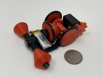
In the demonstration video, I let the mechanism loose on an 8 1/2" by 11" (the size of "standard" notebook paper) by 1/2" thick piece of untreated MDF. As can be seen in the video, using only electro mechanical techniques, when the mechanism approaches the edge of the MDF the conical front wheels allow the front yoke to pivot thus lowering the chassis front to the point where the rotation gear contacts the MDF surface. When this occurs, the mechanism rotates clockwise (as viewed from the top), steers away from the MDF edge, then continues on a new path to the next edge.
As usual, I probably forgot a file or two or who knows what else, so if you have any questions, please do not hesitate to ask as I do make plenty of mistakes.
One final note, I receive no compensation in any form whatsoever for the design, equipment, parts and/or materials used in this mechanism.
Designed using Autodesk Fusion 360, sliced using Cura 4.4.0, and printed in PLA on an Ultimaker 3 Extended and an Ultimaker S5.
I acquired the following parts for this mechanism:
• One 3.7vdc 100ma Lithium Battery (https://www.adafruit.com/product/1570).
• One... JST PH 2-Pin Cable (https://www.adafruit.com/product/3814).
• One N20 6VDC 150RPM gear motor (on line).
• Three R19 O-Rings (23.5mm I.D., 3.5mm section, local hardware store).
You will also need a suitable battery charger.
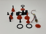
I 3D printed the following parts in PLA at .15mm layer height with 20% infill and no supports:
• Two "Axle, Wheel, Front.stl".
• One "Axle, Wheel, Right Rear.stl".
• One "Axle, Wheel, Rotate.stl".
• One "Axle, Yoke.stl".
• One "Gear, Crown, Axle (1.5m12t).stl".
• One "Gear, Motor (2.2m10t).stl".
• Two "Wheel, Front.stl".
• One "Wheel, Left Rear.stl".
• One "Wheel, Right Rear.stl".
• One "Wheel, Rotate (1.5m12t).stl".
• One "Yoke.stl".
Prior to assembly, test fit and trim, file, drill, sand, etc. all parts as necessary for smooth movement of moving surfaces, and tight fit for non moving surfaces. Depending on you printer, your printer settings and the colors you chose, more or less trimming, filing and/or sanding may be required. Carefully file all edges that contacted the build plate to make absolutely certain that all build plate "ooze" is removed and that all edges are smooth. I used small jewelers files and plenty of patience to perform this step.
This mechanism also uses threaded assembly, so I used a tap and die set (6mm by 1) for thread cleaning.
Assembly.
To assemble the mechanism, I performed the following steps:
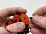
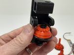
• Slipped an o-ring onto "Wheel, Left Rear.stl", "Wheel, Right Rear.stl" and "Wheel, Rotate (1.5m12t).stl".
• Positioned the rotate wheel assembly in "Chassis.stl" then secured in place with "Axle, Wheel, Rotate.stl" making sure it rotated freely.
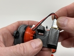
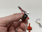
• Soldered the JST connector to the motor such that with power applied, the motor rotates clockwise when viewed from the motor shaft end.
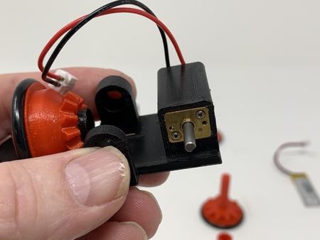
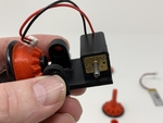
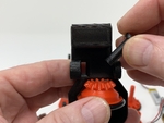
• Pressed the motor assembly into the motor housing in the chassis assembly such that the motor was flush with the motor housing left end.
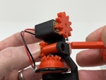
• Pressed "Gear, Motor (2.2m10t).stl" onto the motor shaft.
• Positioned "Gear, Crown, Axle (1.5m12t).stl" in the base assembly then secured in place by press fitting "Wheel, Left Rear.stl" into the gear, then carefully aligned the motor gear with the wheel gear.
• Secured "Wheel, Right Rear.stl" onto the chassis assembly using "Axle, Wheel, Right Rear.stl".
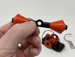
• Secured one "Wheel, Front.stl" to "Yoke.stl" using one "Axle, Wheel, Front.stl", then repeated the process with the remaining front wheel and axle.
• Secured the yoke assembly to the front of the chassis assembly using "Axle, Yoke.stl".
• Secured the LiPo battery to the chassis using double sided tape.
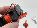
To test the mechanism, I placed it on an 8 1/2" by 11" by 1/2" thick piece of MDF, connected the battery to the motor, and off it went!
And that's how I 3D printed and assembled "No Fall" Toy Mechanism.
I hope you enjoy it!
Designer
Greg Zumwalt3d model description
A mechanism illustrating how the "no fall" battery / windup toys of my childhood operated.Reminiscent of the battery and windup powered "no fall..." toys of my childhood, I designed this "No Fall Toy Mechanism" to illustrate how the battery and windup powered "no fall" toys I was gifted over fifty years ago avoided falling off the edge of a tabletop, countertop, or other elevated surface, without the use of micro controllers, servos and / or electronic sensors.
While designing my version of this mechanism using the computational features of Autodesk Fusion 360 for balance (e.g. "Center of Mass") and a scientific calculator for geometry, I was truly amazed by the skills and talents of the mechanical engineers who designed mechanisms such as this using drafting machines and slide rules over half a century ago.
In the demonstration video, I let the mechanism loose on an 8 1/2" by 11" (the size of "standard" notebook paper) by 1/2" thick piece of untreated MDF. As can be seen in the video, using only electro mechanical techniques, when the mechanism approaches the edge of the MDF the conical front wheels allow the front yoke to pivot thus lowering the chassis front to the point where the rotation gear contacts the MDF surface. When this occurs, the mechanism rotates clockwise (as viewed from the top), steers away from the MDF edge, then continues on a new path to the next edge.
As usual, I probably forgot a file or two or who knows what else, so if you have any questions, please do not hesitate to ask as I do make plenty of mistakes.
One final note, I receive no compensation in any form whatsoever for the design, equipment, parts and/or materials used in this mechanism.
Designed using Autodesk Fusion 360, sliced using Cura 4.4.0, and printed in PLA on an Ultimaker 3 Extended and an Ultimaker S5.
3d model print parameters
Parts.I acquired the following parts for this mechanism:
• One 3.7vdc 100ma Lithium Battery (https://www.adafruit.com/product/1570).
• One... JST PH 2-Pin Cable (https://www.adafruit.com/product/3814).
• One N20 6VDC 150RPM gear motor (on line).
• Three R19 O-Rings (23.5mm I.D., 3.5mm section, local hardware store).
You will also need a suitable battery charger.
I 3D printed the following parts in PLA at .15mm layer height with 20% infill and no supports:
• Two "Axle, Wheel, Front.stl".
• One "Axle, Wheel, Right Rear.stl".
• One "Axle, Wheel, Rotate.stl".
• One "Axle, Yoke.stl".
• One "Gear, Crown, Axle (1.5m12t).stl".
• One "Gear, Motor (2.2m10t).stl".
• Two "Wheel, Front.stl".
• One "Wheel, Left Rear.stl".
• One "Wheel, Right Rear.stl".
• One "Wheel, Rotate (1.5m12t).stl".
• One "Yoke.stl".
Prior to assembly, test fit and trim, file, drill, sand, etc. all parts as necessary for smooth movement of moving surfaces, and tight fit for non moving surfaces. Depending on you printer, your printer settings and the colors you chose, more or less trimming, filing and/or sanding may be required. Carefully file all edges that contacted the build plate to make absolutely certain that all build plate "ooze" is removed and that all edges are smooth. I used small jewelers files and plenty of patience to perform this step.
This mechanism also uses threaded assembly, so I used a tap and die set (6mm by 1) for thread cleaning.
Assembly.
To assemble the mechanism, I performed the following steps:
• Slipped an o-ring onto "Wheel, Left Rear.stl", "Wheel, Right Rear.stl" and "Wheel, Rotate (1.5m12t).stl".
• Positioned the rotate wheel assembly in "Chassis.stl" then secured in place with "Axle, Wheel, Rotate.stl" making sure it rotated freely.
• Soldered the JST connector to the motor such that with power applied, the motor rotates clockwise when viewed from the motor shaft end.
• Pressed the motor assembly into the motor housing in the chassis assembly such that the motor was flush with the motor housing left end.
• Pressed "Gear, Motor (2.2m10t).stl" onto the motor shaft.
• Positioned "Gear, Crown, Axle (1.5m12t).stl" in the base assembly then secured in place by press fitting "Wheel, Left Rear.stl" into the gear, then carefully aligned the motor gear with the wheel gear.
• Secured "Wheel, Right Rear.stl" onto the chassis assembly using "Axle, Wheel, Right Rear.stl".
• Secured one "Wheel, Front.stl" to "Yoke.stl" using one "Axle, Wheel, Front.stl", then repeated the process with the remaining front wheel and axle.
• Secured the yoke assembly to the front of the chassis assembly using "Axle, Yoke.stl".
• Secured the LiPo battery to the chassis using double sided tape.
To test the mechanism, I placed it on an 8 1/2" by 11" by 1/2" thick piece of MDF, connected the battery to the motor, and off it went!
And that's how I 3D printed and assembled "No Fall" Toy Mechanism.
I hope you enjoy it!