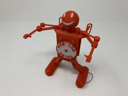
Nutcracker pin walker 3D for print

11559 Views 1 Likes 0 Downloads Download the piece here from 3dforprint
https://youtu.be/j8txVIA9YJA
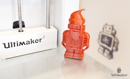
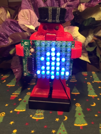
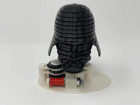
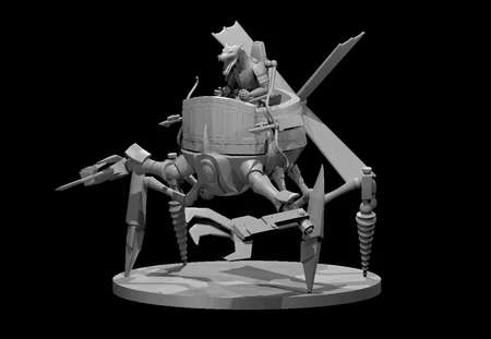
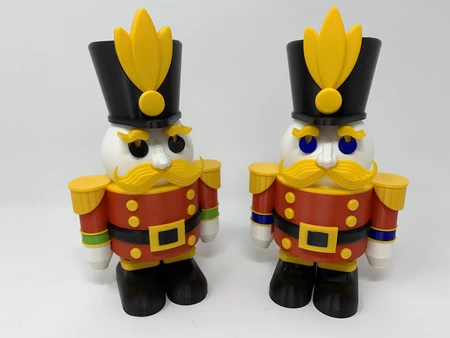
Reminiscent of a static Nutcracker model my father and I created in balsa wood using... one of my favorite childhood Christmas presents, the “Mattel Power Shop” (circa fifty plus years ago), “Robotic Nutcracker Pin Walker” is a 3D printed recreation in pin walker form of the laminated mustache and lathed arms, hands, body, feet and head nutcracker my father taught me how to mill using my power shop many years ago. I was unable to locate our original plans thus this version was recreated from bits and pieces of memories, family photographs and internet searches.
This 3D printed recreation is designed for single extrusion 3D printers thus some color detail pieces are threaded or glued (I used thick cyanoacrylate glue) in place. I also designed this model to print without requiring support material, however if you have access to a dual extrusion printer with PVA used for support, "Base.stl" will require much less clean up after printing. The mechanism that propels this model is very similar to my previous pin walker designs in both 3D printed and purchased parts.
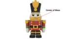
For both longitudinal and lateral stability of a pin walking model of this size, it is important that the center of mass be located over the center of the elliptical path of the pins (from front to back), and centered between the pins (from left to right). As can be seen in the center of mass images as calculated by Autodesk Fusion 360, the center of mass of this model both front to back and side to side satisfies these conditions, yet is slightly top heavy, so I used a lower RPM gear motor in the design for increased stability. With the battery and gear motor I selected for this model, the average power consumption is around 16MA, so it should run a few hours before needing a recharge.
As usual, I probably forgot a file or two or who knows what else, so if you have any questions, please do not hesitate to ask as I do make plenty of mistakes.
One final note, I receive no compensation in any form whatsoever for the design, equipment, parts and/or materials used in this model.
Oh and one final, final note, from Lora and I and our entire family, to you and yours, Merry Christmas!
Designed using Autodesk Fusion 360, sliced using Cura 4.4.0, and printed in PLA on an Ultimaker 2+ Extended, an Ultimaker 3 Extended, and an Ultimaker S5.
I acquired the following parts for this model:
• One 3.7vdc 100ma Lithium Battery (https://www.adafruit.com/product/1570).
• One JST... PH 2-Pin Cable (https://www.adafruit.com/product/3814).
• One N20 6VDC 74RPM gear motor.
• One micro switch (Uxcell a12013100ux0116 High Knob 3P 2 Position 1P2T SPDT Vertical • Slide Switch, 0.5 Amp, 50V DC, 50 Piece, 3 mm).
You will also need a suitable battery charger.
I 3D printed the following parts in PLA at .15mm layer height with 20% infill (unless otherwise noted) and no supports:
• Two "Axle, Body.stl", white.
• Two "Axle, Pin.stl", white.
• One "Axle, Seesaw.stl".
• Four "Band.stl", yellow.
• One "Base.stl" using the Cura 4.4.0 "Gradual Infill" option, black with optional PVA support.
• One "Belt.stl", black.
• Two "Bolt, Shoulder.stl", yellow.
• One "Buckle.stl", yellow.
• Six "Button.stl", yellow.
• One "Cam And Axle.stl", white.
• One "Cam.stl", white.
• Two "Cuff.stl", green.
• One "Eye, Left.stl", black.
• One "Eye, Right.stl", black.
• One "Eyebrow, Left.stl", yellow.
• One "Eyebrow, Right.stl", yellow.
• One "Gear, Crown, Axle.stl", white.
• One "Gear, Crown, Motor.stl", white.
• Two "Hand.stl", white.
• One "Hat, Medallion Button.stl", yellow.
• One "Hat, Medallion.stl", yellow.
• One "Hat, Pin.stl", black.
• One "Hat.stl" using the Cura 4.4.0 "Gradual Infill" option, black.
• One "Head.stl", white.
• One "Leg Band, Left.stl", yellow.•
• One "Leg Band, Right.stl", yellow.
• One "Mustache.stl", yellow.
• Two "Pin", white.
• One "Seesaw.stl", white.
• One "Shoulders.stl", yellow.
• One "Torso, Lower.stl", red.
• One "Torso, Upper.stl", red.
This model is a high precision print and assembly using at times very small precision 3D printed parts in confined spaces. Prior to assembly, test fit and trim, file, drill, sand, etc. all parts as necessary for smooth movement of moving surfaces, and tight fit for non moving surfaces. Depending on you printer, your printer settings and the colors you chose, more or less trimming, filing and/or sanding may be required. Carefully file all edges that contacted the build plate to make absolutely certain that all build plate "ooze" is removed and that all edges are smooth. I used small jewelers files and plenty of patience to perform this step.
This model also uses threaded assembly, so I used a tap and die set (6mm by 1) for thread cleaning.
Assemble the Hat.
To assemble the Hat, I performed the following steps:
• Pressed "Hat, Medallion Button.stl" into "Hat.stl".
• Glued "Hat, Medallion.stl" to the hat assembly.
• Glued "Hat, Pin.stl" to the hat assembly.
Assemble the Head.
To assemble the head, I performed the following steps:
• Pressed and glued "Eye, Right.stl", "Eye, Left.stl", "Eyebrow, Right.stl" and "Eyebrow Left.stl" into "Head.stl".
• Glued "Mustache.stl" onto the assembly under the nose.
Attach the Hat Assembly to the Head Assembly.
To attach the hat assembly to the head assembly, using the hat pin as a centering guide, I glued the two assemblies together.
Assemble the Body.
To assemble the body, I performed the following steps:
• Pressed four "Button.stl" into "Torso, Upper.stl".
• Pressed"Buckle.stl" onto "Belt.stl".
• Slid the belt assembly onto the torso assembly aligning the slots in the belt assembly with the legs on the torso assembly.
• Pressed "Shoulders.stl" onto the torso assembly.
• Placed one "Band.stl" onto one of the legs of the torso assembly.
• Slid one "Bolt, Shoulder.stl" up through the shoulder, torso and band.
• Placed one "Band.stl" onto the remaining leg of the torso assembly.
• Slid the remaining "Bolt, Should.stl" up through the shoulder, torso and band.
• Place one "Cuff.stl" onto each of the shoulder bolts.
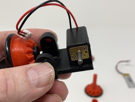
Wire the Motor, Switch and JST Connector.
To wire the motor, switch and JST connector, I performed the following steps:
• Cut the black wire on the JST connector to 20mm in length, stripped and tinned the end, and soldered it to the center terminal of the switch.
• Tripped and tinned the ends of the remaining 80mm section of black wire, and soldered it from one outside terminal of the switch to the "-" motor terminal.
• Soldered the red wire from the JST connector to the motor "+" terminal.
After wiring, I connected the battery to the JST connector, turned the switch on, and verified that the motor shaft rotated clockwise as viewed from the motor shaft end of the motor (if not, I reversed the motor wiring). I then turned the switch off and disconnected the battery.
Assemble the Base.
To assemble the base, I performed the following steps:
• Pressed the remaining two "Button.stl" into "Torso, Lower.stl".
• Pressed the motor into position up from the feet side of "Base.stl" such that the motor shaft was 3mm above the surface of the motor crown gear plate.
• Positioned the torso assembly onto the base assembly (centered over the lower holes of the bass assembly base, buttons forward), then secured it in place using both "Axle, Body.stl", making sure the lower torso swung freely on the axles.
• Ran the switch, JST connector and wires up through the lower torso assembly then pressed the switch into the lower torso.
• Pressed "Gear, Crown, Motor.stl" onto the exposed motor shaft flush with the end and secured in place with a small dot of cyanoacrylate glue.
• Positioned "Gear, Crown, Axle.stl" inside the base assembly over the smaller axle hole.
• Slid the hexagonal shaft of "Cam and Axle.stl" into the base assembly larger axle hole.
• Pressed the hexagonal axle shaft through the axle gear and out the smaller axle hole in the base assembly (this must be a tight fit, if not, I added a small dot of cyanoacrylate glue).
• Pressed "Cam.stl" onto the hexagonal shaft end of the axle assembly such that the cam was 180 degrees from the "Cam And Axle.stl" component (this must be a tight fit, if not, I added a small dot of cyanoacrylate glue).
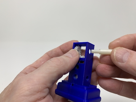
• Slid one "Pin" into the base assembly and positioned the cam ring over the cam then secured in place with one "Axle, Pin.stl".
• Slid the remaining "Pin.stl" into the base assembly and positioned the cam ring over the cam then secured in place with the remaining "Axle, Pin.stl".
• Rotated the motor gear by hand until the leg pins were level (one cam straight forward, remaining straight backward).
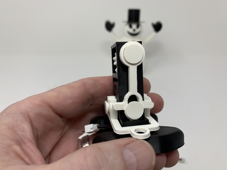
• Positioned "Seesaw.stl" over the upper threaded hole on the base assembly and secured in place with "Axle, Seesaw.stl", making sure the center two teeth of the seesaw surrounded the center tooth on the lower torso gear.
Final Assembly.
For final assembly, I performed the following steps:
• Secured the battery in place using double sided tape, then plugged the battery into the JST connector.
• While holding the body assembly upside down, slid the base assembly into the body assembly.
• Positioned one "Band.stl" over the shoulder bolt in the body assembly, aligning the band with the contour of the base torso.
• Positioned one "Hand.stl" over the threads of the shoulder bolt in the body assembly with the grip over the torso and secured in place by rotating the shoulder bolt clockwise (the bolt, upper torso, band, cuff, band and hand form a "vise" mechanism which secures the base assembly to the body assembly).
• Repeated the previous step for the remaining hand.
• Secured the head to the assembly using small dots of cyanoacrylate glue.
• Secured the two "Leg Band, Left.stl" and "Leg Band, Right.stl" to the base using small dots of cyanoacrylate glue.
• Turned on the power, and off this nutcracker went pin walking!
And that's how I 3D printed and assembled Nutcracker Pin Walker.
I hope you enjoyed it!
Designer
Greg Zumwalt3d model description
A pin walker in Nutcracker attire.https://youtu.be/j8txVIA9YJA
Reminiscent of a static Nutcracker model my father and I created in balsa wood using... one of my favorite childhood Christmas presents, the “Mattel Power Shop” (circa fifty plus years ago), “Robotic Nutcracker Pin Walker” is a 3D printed recreation in pin walker form of the laminated mustache and lathed arms, hands, body, feet and head nutcracker my father taught me how to mill using my power shop many years ago. I was unable to locate our original plans thus this version was recreated from bits and pieces of memories, family photographs and internet searches.
This 3D printed recreation is designed for single extrusion 3D printers thus some color detail pieces are threaded or glued (I used thick cyanoacrylate glue) in place. I also designed this model to print without requiring support material, however if you have access to a dual extrusion printer with PVA used for support, "Base.stl" will require much less clean up after printing. The mechanism that propels this model is very similar to my previous pin walker designs in both 3D printed and purchased parts.
For both longitudinal and lateral stability of a pin walking model of this size, it is important that the center of mass be located over the center of the elliptical path of the pins (from front to back), and centered between the pins (from left to right). As can be seen in the center of mass images as calculated by Autodesk Fusion 360, the center of mass of this model both front to back and side to side satisfies these conditions, yet is slightly top heavy, so I used a lower RPM gear motor in the design for increased stability. With the battery and gear motor I selected for this model, the average power consumption is around 16MA, so it should run a few hours before needing a recharge.
As usual, I probably forgot a file or two or who knows what else, so if you have any questions, please do not hesitate to ask as I do make plenty of mistakes.
One final note, I receive no compensation in any form whatsoever for the design, equipment, parts and/or materials used in this model.
Oh and one final, final note, from Lora and I and our entire family, to you and yours, Merry Christmas!
Designed using Autodesk Fusion 360, sliced using Cura 4.4.0, and printed in PLA on an Ultimaker 2+ Extended, an Ultimaker 3 Extended, and an Ultimaker S5.
3d model print parameters
Parts.I acquired the following parts for this model:
• One 3.7vdc 100ma Lithium Battery (https://www.adafruit.com/product/1570).
• One JST... PH 2-Pin Cable (https://www.adafruit.com/product/3814).
• One N20 6VDC 74RPM gear motor.
• One micro switch (Uxcell a12013100ux0116 High Knob 3P 2 Position 1P2T SPDT Vertical • Slide Switch, 0.5 Amp, 50V DC, 50 Piece, 3 mm).
You will also need a suitable battery charger.
I 3D printed the following parts in PLA at .15mm layer height with 20% infill (unless otherwise noted) and no supports:
• Two "Axle, Body.stl", white.
• Two "Axle, Pin.stl", white.
• One "Axle, Seesaw.stl".
• Four "Band.stl", yellow.
• One "Base.stl" using the Cura 4.4.0 "Gradual Infill" option, black with optional PVA support.
• One "Belt.stl", black.
• Two "Bolt, Shoulder.stl", yellow.
• One "Buckle.stl", yellow.
• Six "Button.stl", yellow.
• One "Cam And Axle.stl", white.
• One "Cam.stl", white.
• Two "Cuff.stl", green.
• One "Eye, Left.stl", black.
• One "Eye, Right.stl", black.
• One "Eyebrow, Left.stl", yellow.
• One "Eyebrow, Right.stl", yellow.
• One "Gear, Crown, Axle.stl", white.
• One "Gear, Crown, Motor.stl", white.
• Two "Hand.stl", white.
• One "Hat, Medallion Button.stl", yellow.
• One "Hat, Medallion.stl", yellow.
• One "Hat, Pin.stl", black.
• One "Hat.stl" using the Cura 4.4.0 "Gradual Infill" option, black.
• One "Head.stl", white.
• One "Leg Band, Left.stl", yellow.•
• One "Leg Band, Right.stl", yellow.
• One "Mustache.stl", yellow.
• Two "Pin", white.
• One "Seesaw.stl", white.
• One "Shoulders.stl", yellow.
• One "Torso, Lower.stl", red.
• One "Torso, Upper.stl", red.
This model is a high precision print and assembly using at times very small precision 3D printed parts in confined spaces. Prior to assembly, test fit and trim, file, drill, sand, etc. all parts as necessary for smooth movement of moving surfaces, and tight fit for non moving surfaces. Depending on you printer, your printer settings and the colors you chose, more or less trimming, filing and/or sanding may be required. Carefully file all edges that contacted the build plate to make absolutely certain that all build plate "ooze" is removed and that all edges are smooth. I used small jewelers files and plenty of patience to perform this step.
This model also uses threaded assembly, so I used a tap and die set (6mm by 1) for thread cleaning.
Assemble the Hat.
To assemble the Hat, I performed the following steps:
• Pressed "Hat, Medallion Button.stl" into "Hat.stl".
• Glued "Hat, Medallion.stl" to the hat assembly.
• Glued "Hat, Pin.stl" to the hat assembly.
Assemble the Head.
To assemble the head, I performed the following steps:
• Pressed and glued "Eye, Right.stl", "Eye, Left.stl", "Eyebrow, Right.stl" and "Eyebrow Left.stl" into "Head.stl".
• Glued "Mustache.stl" onto the assembly under the nose.
Attach the Hat Assembly to the Head Assembly.
To attach the hat assembly to the head assembly, using the hat pin as a centering guide, I glued the two assemblies together.
Assemble the Body.
To assemble the body, I performed the following steps:
• Pressed four "Button.stl" into "Torso, Upper.stl".
• Pressed"Buckle.stl" onto "Belt.stl".
• Slid the belt assembly onto the torso assembly aligning the slots in the belt assembly with the legs on the torso assembly.
• Pressed "Shoulders.stl" onto the torso assembly.
• Placed one "Band.stl" onto one of the legs of the torso assembly.
• Slid one "Bolt, Shoulder.stl" up through the shoulder, torso and band.
• Placed one "Band.stl" onto the remaining leg of the torso assembly.
• Slid the remaining "Bolt, Should.stl" up through the shoulder, torso and band.
• Place one "Cuff.stl" onto each of the shoulder bolts.
Wire the Motor, Switch and JST Connector.
To wire the motor, switch and JST connector, I performed the following steps:
• Cut the black wire on the JST connector to 20mm in length, stripped and tinned the end, and soldered it to the center terminal of the switch.
• Tripped and tinned the ends of the remaining 80mm section of black wire, and soldered it from one outside terminal of the switch to the "-" motor terminal.
• Soldered the red wire from the JST connector to the motor "+" terminal.
After wiring, I connected the battery to the JST connector, turned the switch on, and verified that the motor shaft rotated clockwise as viewed from the motor shaft end of the motor (if not, I reversed the motor wiring). I then turned the switch off and disconnected the battery.
Assemble the Base.
To assemble the base, I performed the following steps:
• Pressed the remaining two "Button.stl" into "Torso, Lower.stl".
• Pressed the motor into position up from the feet side of "Base.stl" such that the motor shaft was 3mm above the surface of the motor crown gear plate.
• Positioned the torso assembly onto the base assembly (centered over the lower holes of the bass assembly base, buttons forward), then secured it in place using both "Axle, Body.stl", making sure the lower torso swung freely on the axles.
• Ran the switch, JST connector and wires up through the lower torso assembly then pressed the switch into the lower torso.
• Pressed "Gear, Crown, Motor.stl" onto the exposed motor shaft flush with the end and secured in place with a small dot of cyanoacrylate glue.
• Positioned "Gear, Crown, Axle.stl" inside the base assembly over the smaller axle hole.
• Slid the hexagonal shaft of "Cam and Axle.stl" into the base assembly larger axle hole.
• Pressed the hexagonal axle shaft through the axle gear and out the smaller axle hole in the base assembly (this must be a tight fit, if not, I added a small dot of cyanoacrylate glue).
• Pressed "Cam.stl" onto the hexagonal shaft end of the axle assembly such that the cam was 180 degrees from the "Cam And Axle.stl" component (this must be a tight fit, if not, I added a small dot of cyanoacrylate glue).
• Slid one "Pin" into the base assembly and positioned the cam ring over the cam then secured in place with one "Axle, Pin.stl".
• Slid the remaining "Pin.stl" into the base assembly and positioned the cam ring over the cam then secured in place with the remaining "Axle, Pin.stl".
• Rotated the motor gear by hand until the leg pins were level (one cam straight forward, remaining straight backward).
• Positioned "Seesaw.stl" over the upper threaded hole on the base assembly and secured in place with "Axle, Seesaw.stl", making sure the center two teeth of the seesaw surrounded the center tooth on the lower torso gear.
Final Assembly.
For final assembly, I performed the following steps:
• Secured the battery in place using double sided tape, then plugged the battery into the JST connector.
• While holding the body assembly upside down, slid the base assembly into the body assembly.
• Positioned one "Band.stl" over the shoulder bolt in the body assembly, aligning the band with the contour of the base torso.
• Positioned one "Hand.stl" over the threads of the shoulder bolt in the body assembly with the grip over the torso and secured in place by rotating the shoulder bolt clockwise (the bolt, upper torso, band, cuff, band and hand form a "vise" mechanism which secures the base assembly to the body assembly).
• Repeated the previous step for the remaining hand.
• Secured the head to the assembly using small dots of cyanoacrylate glue.
• Secured the two "Leg Band, Left.stl" and "Leg Band, Right.stl" to the base using small dots of cyanoacrylate glue.
• Turned on the power, and off this nutcracker went pin walking!
And that's how I 3D printed and assembled Nutcracker Pin Walker.
I hope you enjoyed it!