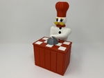
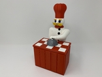
The "magic chef", a 3d printed automata 3D for print


22958 Views 1 Likes 0 Downloads Download the piece here from 3dforprint
I truly enjoy automata and after viewing the works of automata creators such as positivelycreative, Keith Newstead ...and Paul Spooner, I decided to attempt to create a series of "illusion" themed automata, the "Magic Chef" being my first.
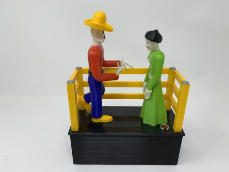
In this automata, a chef presents food to an imaginary customer (the viewer) only to be rejected, whereas the chef lowers the "cloche" styled food dome then raises it to "magically" present yet another food selection.
As usual, I probably forgot a file or two or who knows what else, so if you have any questions, please do not hesitate to ask as I do make plenty of mistakes.
One final note, I receive no compensation in any form whatsoever for the design, equipment, parts and/or materials used in this model.
Designed using Autodesk Fusion 360, sliced using Cura 4.4.1, and printed in PLA on an Ultimaker 2+ Extended, and Ultimaker 3 Extended and an Ultimaker S5.
I acquired the following parts for this mechanism:
• One N20 6VDC 35RPM gear motor (on line).
• Sixteen 3mm (diameter) by 1.5mm (thi...ckness) neodymium magnets (local hobby shop).
• Four 6mm (diameter) by 1.5mm (thickness) neodymium magnets (local hobby shop).
• Six miniature doll house food items (these items must be less than 18mm square and less than 6mm tall, stickers may be used as well, I obtained mine from the grandkids doll house!).
• 3.0 to 4.5vdc 100ma power supply.
• A wired connector suitable for connecting the motor to the power supply.
I 3D printed the parts shown in the attached file "Magic Chef 3D Printed Parts.pdf" at .15mm layer height.
This mechanism is a high precision print and assembly using at times very small precision 3D printed parts in confined spaces. Prior to assembly, test fit and trim, file, drill, sand, etc. all parts as necessary for smooth movement of moving surfaces, and tight fit for non moving surfaces. Depending on you printer, your printer settings and the colors you chose, more or less trimming, filing, drilling and/or sanding may be required. Carefully file all edges that contacted the build plate to make absolutely certain that all build plate "ooze" is removed and that all edges are smooth. I used small jewelers files and plenty of patience to perform this step.
This mechanism also uses threaded assembly, so I used a tap and die set (6mm by 1, 8mm by 1.25) for thread cleaning.
Carousel Assembly.
To prepare the carousel, I performed the following steps:
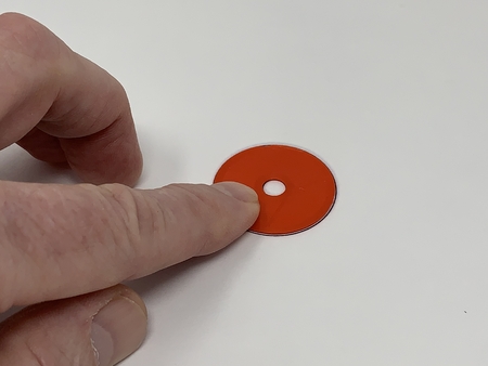
• Selected my six food items, then used a ball grinder attachment on my hand held motor tool to remove excess material from the underside of each food item until they all weighed as close to the same as possible.
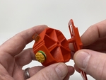
• Glued the six food items onto "Wheel.stl" using thick cyanoacrylate glue, centering each on its respective mounting surface.
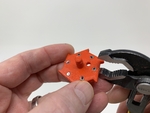
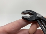
To prepare the ratchets, I performed the following steps:
• Stacked all 3mm (diameter) by 1.5mm (thick) magnets end to end.
• Used an indelible ink marker to mark the top of the top magnet on the stack.
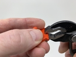
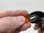
• Removed the top magnet from the stack and attached the marked side to the upper jaw of my small slip joint pliers.
• Pressed the magnet into one hole on "Ratchet.stl".
• Repeated these steps for the remaining five magnets.
• Repeated these steps for "Ratchet(Mirror).stl".
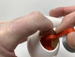
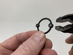
To prepare the springs, I performed the following steps:
• Marked the top of the top magnet on the stack.
• Removed the top magnet and attached the marked side to the upper jaw of my small slip joint pliers.
• Pressed the magnet into one hole in "Spring.stl".
• Pressed a second magnet into the remaining hole in "Spring.stl"
• Repeated these steps for the remaining "Spring.stl".
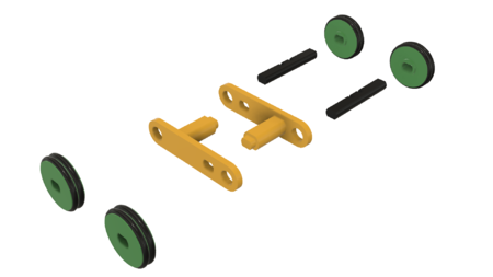
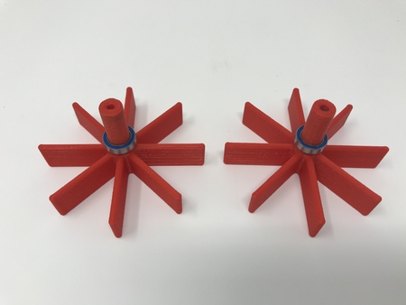
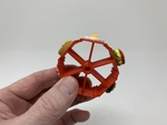
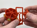
To assemble the carousel, I performed the following steps:
• Slid the ratchet assembly through "Guide.stl" then threaded it into the wheel assembly to the position and orientation as shown.
• Slid the ratchet(mirror) assembly through "Guide(Mirror).stl" then threaded it into the remaining side of the wheel assembly to the position and orientation as shown.
• Secured one spring assembly to the carousel assembly guide using "Bolt, Spring, Long.stl".
• Secured the remaining spring assembly to the carousel assembly guide(mirror) using one "Bolt, Spring, Short.stl".
Base Assembly.
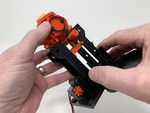
To assemble the base, I performed the following steps:
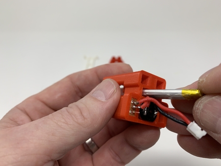
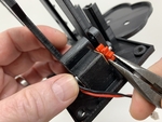
• Soldered a suitable wired connector to the motor, applied power, and verified that the motor rotated counter-clockwise as viewed from the motor shaft end of the motor (if not, I reversed the wires), then removed power.
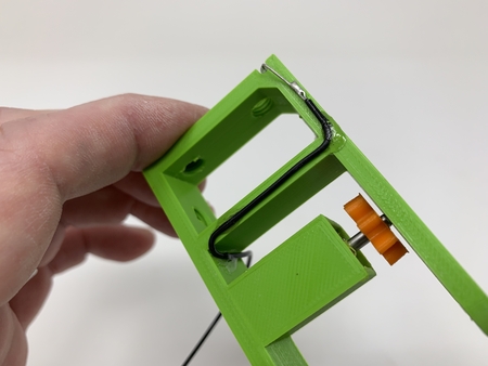
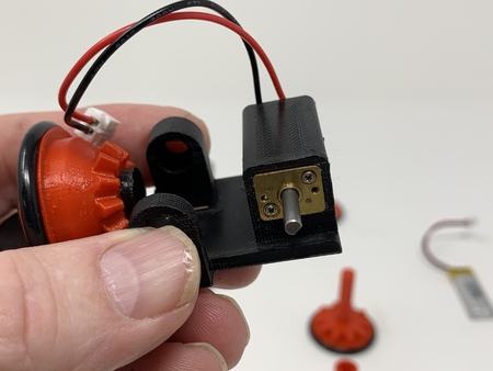
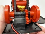
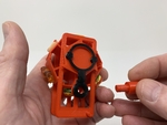
• Pressed the motor part way into "Base.stl", positioned "Gear, Motor (1.5m 8t).stl" in the axle tower slot aligned with the motor shaft, then pressed the motor shaft through the hole in the gear.
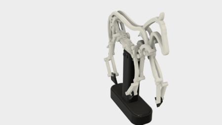
• Slide the carousel assembly into the base assembly towers such that the long spring bolt is closest to the chef feet mount. This assembly must slide up and down with ease in the guide slots.
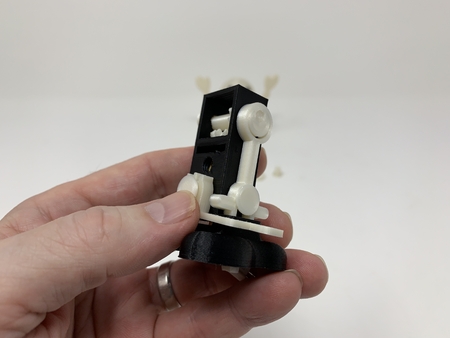
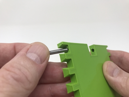
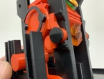
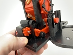
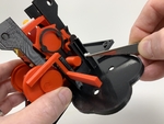
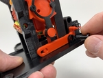
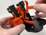
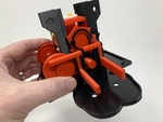
• Positioned "Arm, Guide(Mirror).stl" as shown then secured in place with one "Axle, Arm, Guide.stl".
• Positioned "Arm, Guide.stl" as shown then secured in place with the remaining "Axle, Arm, Guide.stl".
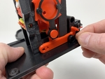
• Positioned one "Pawl.stl" as shown then secured in place with one "Axle, Pawl.stl" making sure the pawl swung freely about the axle.
• Positioned the remaining "Pawl.stl" as shown then secured in place with the remaining "Axle, Pawl.stl" making sure the pawl swung freely about the axle.
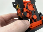
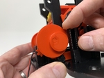
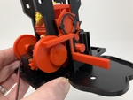
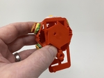
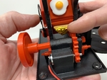
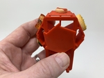
• Slid "Cam And Axle.stl" into the axle hole as shown.
• Positioned "Gear, Axle (1.5m 12t).stl" in the axle tower slot then slid the axle through the axle gear.
• Positioned "Cam, Guide.stl" over the axle as shown the slid the axle through the guide cam.
• Positioned "Cam, Arm.stl" over the axle in the orientation as shown then pressed in place.
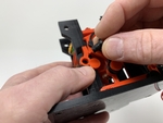
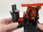
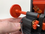
• Slid "Lift, Rack, Arm.stl" into the position as shown.
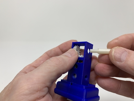
• Placed a few small tufts of cotton in the guide slot in the base assembly for the head rack lift arm (the cotton acts as a shock absorber when the head drops).
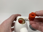
• Slid "Lift, Rack, Head.stl" into the head rack lift arm guide as shown.
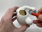
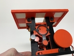
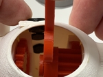
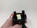
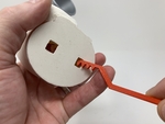
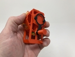
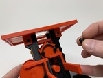
• Secured "Top, Dual Extrusion.3mf" to the base assembly using four "Bolt (6mm by 1 by 5).stl".
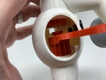
At this point, I applied power to the mechanism to make sure the carousel 60 degrees per each lowering and raising of the carousel, and when completely raised a food item was centered in the hole in the top. If not, carefully adjust the position of the two ratchets making sure that both are aligned and oriented to allow food centering. After alignment and test, I removed power.
Chef Components Assembly.
For assembly of the chef components, I performed the following steps:
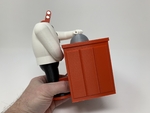
• Attached a 30mm long piece of double sided tape between the rack guide towers on "Chef, Pants.stl".
• Positioned the pants on the base assembly and temporarily secured in place with two "Bolt (6mm by 1 by 9).stl".
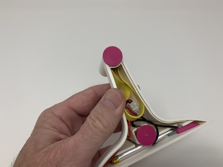
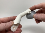
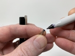
• Installed two 6mm diameter magnets in "Chef, Head.stl" and the remaining two in "Gear, • Head (1.5m 12t).stl" using the same process I used for installing the 3mm diameter magnets in the ratchets and springs.
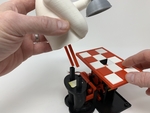
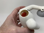
• Pressed "Cover With Hand.3mf" into "Chef, Arm, Left.stl" and temporarily secured in place using double sided tape.
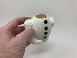
• Pressed four "Chef, Button.stl" into "Chef, Coat, White.stl" and secured in place using thick cyanoacrylate glue.
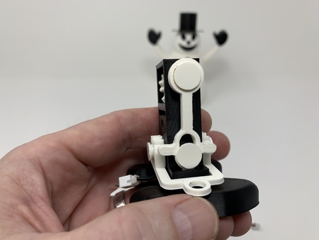
• Positioned the left arm assembly on the left shoulder of the coat and secured in place with "Gear, Arm (1.5m 12t).stl".
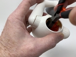
• Positioned "Axle, Gear, Head.stl" into "Gear, Head (1.5m 12t).stl", slid the assembly into the top hole of the coat assembly oriented as shown, then carefully threaded the axle fully into the coat initially using my left index finger, then finishing using needle nose pliers.
• With the arm in the full down position, installed one "Rack.stl" between the arm gear and coat guide.
• With the head gear in the full forward position, installed the remaining "Rack.stl" between the head gear and coat guide.
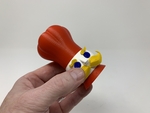
• Attached "Chef, Head, Eye, Left.stl", "Chef, Head, Eye, Right.stl", "Chef Head, Eyebrow, Left.stl", "Chef, Head, Eyebrow, Right.stl", "Chef, Head, Mustache.stl", "Chef, Head, Collar.stl" and "Chef, Hat.stl" to "Chef, Head, Head.stl" using thick cyanoacrylate glue.
Final Assembly.
For final assembly, I performed the following steps:
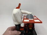
• Carefully positioned the chef coat assembly over the chef pants, aligned the racks with the rack guides, then pressed the coat assembly onto the pants firmly to connect the two using the previously attached double sided tape.
• Adjusted the left arm gear such that the cover with hand is barely contacting the top, then glued the cover with hand to the left arm using thick cyanoacrylate glue.
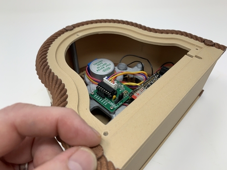
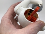
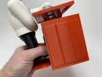
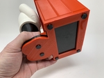
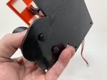
• Removed the two bolts holding the chef to the base, slid "Enclosure.stl" up from the bottom of the base making sure the upper edge of the enclosure was fully inserted into the slot on the underside of the top, then secured the chef and enclosure to the base using the six "Bolt (6mm by 1 by 9).stl.
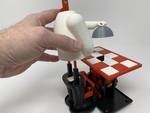
• Finally, I pressed the head assembly onto the head gear, applied power to the motor, then sat back and watched the show!
And that is how I 3D printed and assembled my "Magic Chef".
I hope you enjoyed it!
Designer
Greg Zumwalt3d model description
A 3D printed magic chef automata,I truly enjoy automata and after viewing the works of automata creators such as positivelycreative, Keith Newstead ...and Paul Spooner, I decided to attempt to create a series of "illusion" themed automata, the "Magic Chef" being my first.
In this automata, a chef presents food to an imaginary customer (the viewer) only to be rejected, whereas the chef lowers the "cloche" styled food dome then raises it to "magically" present yet another food selection.
As usual, I probably forgot a file or two or who knows what else, so if you have any questions, please do not hesitate to ask as I do make plenty of mistakes.
One final note, I receive no compensation in any form whatsoever for the design, equipment, parts and/or materials used in this model.
Designed using Autodesk Fusion 360, sliced using Cura 4.4.1, and printed in PLA on an Ultimaker 2+ Extended, and Ultimaker 3 Extended and an Ultimaker S5.
3d model print parameters
Parts.I acquired the following parts for this mechanism:
• One N20 6VDC 35RPM gear motor (on line).
• Sixteen 3mm (diameter) by 1.5mm (thi...ckness) neodymium magnets (local hobby shop).
• Four 6mm (diameter) by 1.5mm (thickness) neodymium magnets (local hobby shop).
• Six miniature doll house food items (these items must be less than 18mm square and less than 6mm tall, stickers may be used as well, I obtained mine from the grandkids doll house!).
• 3.0 to 4.5vdc 100ma power supply.
• A wired connector suitable for connecting the motor to the power supply.
I 3D printed the parts shown in the attached file "Magic Chef 3D Printed Parts.pdf" at .15mm layer height.
This mechanism is a high precision print and assembly using at times very small precision 3D printed parts in confined spaces. Prior to assembly, test fit and trim, file, drill, sand, etc. all parts as necessary for smooth movement of moving surfaces, and tight fit for non moving surfaces. Depending on you printer, your printer settings and the colors you chose, more or less trimming, filing, drilling and/or sanding may be required. Carefully file all edges that contacted the build plate to make absolutely certain that all build plate "ooze" is removed and that all edges are smooth. I used small jewelers files and plenty of patience to perform this step.
This mechanism also uses threaded assembly, so I used a tap and die set (6mm by 1, 8mm by 1.25) for thread cleaning.
Carousel Assembly.
To prepare the carousel, I performed the following steps:
• Selected my six food items, then used a ball grinder attachment on my hand held motor tool to remove excess material from the underside of each food item until they all weighed as close to the same as possible.
• Glued the six food items onto "Wheel.stl" using thick cyanoacrylate glue, centering each on its respective mounting surface.
To prepare the ratchets, I performed the following steps:
• Stacked all 3mm (diameter) by 1.5mm (thick) magnets end to end.
• Used an indelible ink marker to mark the top of the top magnet on the stack.
• Removed the top magnet from the stack and attached the marked side to the upper jaw of my small slip joint pliers.
• Pressed the magnet into one hole on "Ratchet.stl".
• Repeated these steps for the remaining five magnets.
• Repeated these steps for "Ratchet(Mirror).stl".
To prepare the springs, I performed the following steps:
• Marked the top of the top magnet on the stack.
• Removed the top magnet and attached the marked side to the upper jaw of my small slip joint pliers.
• Pressed the magnet into one hole in "Spring.stl".
• Pressed a second magnet into the remaining hole in "Spring.stl"
• Repeated these steps for the remaining "Spring.stl".
To assemble the carousel, I performed the following steps:
• Slid the ratchet assembly through "Guide.stl" then threaded it into the wheel assembly to the position and orientation as shown.
• Slid the ratchet(mirror) assembly through "Guide(Mirror).stl" then threaded it into the remaining side of the wheel assembly to the position and orientation as shown.
• Secured one spring assembly to the carousel assembly guide using "Bolt, Spring, Long.stl".
• Secured the remaining spring assembly to the carousel assembly guide(mirror) using one "Bolt, Spring, Short.stl".
Base Assembly.
To assemble the base, I performed the following steps:
• Soldered a suitable wired connector to the motor, applied power, and verified that the motor rotated counter-clockwise as viewed from the motor shaft end of the motor (if not, I reversed the wires), then removed power.
• Pressed the motor part way into "Base.stl", positioned "Gear, Motor (1.5m 8t).stl" in the axle tower slot aligned with the motor shaft, then pressed the motor shaft through the hole in the gear.
• Slide the carousel assembly into the base assembly towers such that the long spring bolt is closest to the chef feet mount. This assembly must slide up and down with ease in the guide slots.
• Positioned "Arm, Guide(Mirror).stl" as shown then secured in place with one "Axle, Arm, Guide.stl".
• Positioned "Arm, Guide.stl" as shown then secured in place with the remaining "Axle, Arm, Guide.stl".
• Positioned one "Pawl.stl" as shown then secured in place with one "Axle, Pawl.stl" making sure the pawl swung freely about the axle.
• Positioned the remaining "Pawl.stl" as shown then secured in place with the remaining "Axle, Pawl.stl" making sure the pawl swung freely about the axle.
• Slid "Cam And Axle.stl" into the axle hole as shown.
• Positioned "Gear, Axle (1.5m 12t).stl" in the axle tower slot then slid the axle through the axle gear.
• Positioned "Cam, Guide.stl" over the axle as shown the slid the axle through the guide cam.
• Positioned "Cam, Arm.stl" over the axle in the orientation as shown then pressed in place.
• Slid "Lift, Rack, Arm.stl" into the position as shown.
• Placed a few small tufts of cotton in the guide slot in the base assembly for the head rack lift arm (the cotton acts as a shock absorber when the head drops).
• Slid "Lift, Rack, Head.stl" into the head rack lift arm guide as shown.
• Secured "Top, Dual Extrusion.3mf" to the base assembly using four "Bolt (6mm by 1 by 5).stl".
At this point, I applied power to the mechanism to make sure the carousel 60 degrees per each lowering and raising of the carousel, and when completely raised a food item was centered in the hole in the top. If not, carefully adjust the position of the two ratchets making sure that both are aligned and oriented to allow food centering. After alignment and test, I removed power.
Chef Components Assembly.
For assembly of the chef components, I performed the following steps:
• Attached a 30mm long piece of double sided tape between the rack guide towers on "Chef, Pants.stl".
• Positioned the pants on the base assembly and temporarily secured in place with two "Bolt (6mm by 1 by 9).stl".
• Installed two 6mm diameter magnets in "Chef, Head.stl" and the remaining two in "Gear, • Head (1.5m 12t).stl" using the same process I used for installing the 3mm diameter magnets in the ratchets and springs.
• Pressed "Cover With Hand.3mf" into "Chef, Arm, Left.stl" and temporarily secured in place using double sided tape.
• Pressed four "Chef, Button.stl" into "Chef, Coat, White.stl" and secured in place using thick cyanoacrylate glue.
• Positioned the left arm assembly on the left shoulder of the coat and secured in place with "Gear, Arm (1.5m 12t).stl".
• Positioned "Axle, Gear, Head.stl" into "Gear, Head (1.5m 12t).stl", slid the assembly into the top hole of the coat assembly oriented as shown, then carefully threaded the axle fully into the coat initially using my left index finger, then finishing using needle nose pliers.
• With the arm in the full down position, installed one "Rack.stl" between the arm gear and coat guide.
• With the head gear in the full forward position, installed the remaining "Rack.stl" between the head gear and coat guide.
• Attached "Chef, Head, Eye, Left.stl", "Chef, Head, Eye, Right.stl", "Chef Head, Eyebrow, Left.stl", "Chef, Head, Eyebrow, Right.stl", "Chef, Head, Mustache.stl", "Chef, Head, Collar.stl" and "Chef, Hat.stl" to "Chef, Head, Head.stl" using thick cyanoacrylate glue.
Final Assembly.
For final assembly, I performed the following steps:
• Carefully positioned the chef coat assembly over the chef pants, aligned the racks with the rack guides, then pressed the coat assembly onto the pants firmly to connect the two using the previously attached double sided tape.
• Adjusted the left arm gear such that the cover with hand is barely contacting the top, then glued the cover with hand to the left arm using thick cyanoacrylate glue.
• Removed the two bolts holding the chef to the base, slid "Enclosure.stl" up from the bottom of the base making sure the upper edge of the enclosure was fully inserted into the slot on the underside of the top, then secured the chef and enclosure to the base using the six "Bolt (6mm by 1 by 9).stl.
• Finally, I pressed the head assembly onto the head gear, applied power to the motor, then sat back and watched the show!
And that is how I 3D printed and assembled my "Magic Chef".
I hope you enjoyed it!