Wifi paddle boat 3D for print


18690 Views 1 Likes 1 Downloads Download the piece here from 3dforprint
Summer is in full swing in Oklahoma and the kids, grandkids, nieces, nephews and, well, just about e...veryone we know is in Lake Zumwalt to cool down. My wife has purchased enough pool toys to fill Lake Zumwalt, so I figured I would join the pool toy fray with WiFi Paddle Boat.
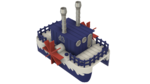
WiFi Paddle Boat is a paddle boat controlled via wifi using a smart phone, tablet or other touch enabled device. WiFi Paddle Boat creates a wifi access point (much like the small sport cameras) that you connect to via your wifi enabled device wifi settings. Then, using your wifi touch enabled device web browser, you simply navigate to the WiFi Paddle Boat web page and off you go! The controls for WiFi Paddle Boat are identical to those of my "Lady Buggy" and "Santa Sleigh" designs so it's easy for the grandkids to operate.
A word of caution; I designed WiFi Paddle Boat to be "splash resistant" not "water proof", so if a rogue wave, grandchild, niece, nephew, etc., "submarines" WiFi Paddle Boat, well good luck.
As usual, I probably forgot a file or two or who knows what else, so if you have any questions, please do not hesitate to ask as I do make mistakes in plenty.
Designed using Autodesk Fusion 360, sliced using Cura 3.4.1, and printed in PLA on both and Ultimaker 2+ Extended and an Ultimaker 3 Extended.
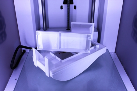
Before you begin, note that WiFi Paddle Boat contains large, flat components that may not fit your build are...a and if they do, warping can become a significant issue so use a brim and your best techniques for build plate adhesion. Note also that there are some thin walled components, some as thin as .8mm, so before printing test each part using your slicer in layer mode to confirm your printers ability to print the parts. And finally, the design requires that the motors, bearings and paddles must align on axis as accurately as possible, so print "Deck.stl" with supports at your highest resolution, then be prepared to carefully file the bearing mounts for a smooth, round, yet friction fit surface.
I purchased the following parts for WiFi Paddle Boat:
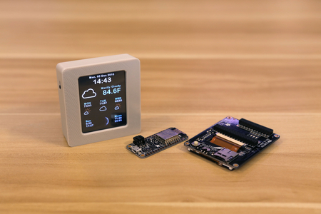
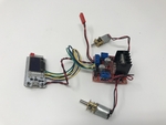
1 Heltec WiFi Kit 32 with Oled display (on line).
1 Timesetl L298N Motor Drive Controller (on line).
2 300 RPM 6 VDC Mini Gear Motors (on line).
4 10 by 15 by 4mm sealed ball bearings (I used a ProtekRC PTK-10046, local hobby shop).
1 Ares AZSZ2503 1200 mAh 2-Cell/2S 7.4V 25C Lipo Battery (local hobby shop).
JST Female Connector (sized for battery, local hobby shop).
You will also need cyanoacrylate glue, acrylic caulk, needle nose pliers and assorted precision hand tools, jewelers files, wire cutters, wire strippers, solder and soldering iron, and maybe clear PLA safe spray paint.
I printed "Deck.stl" and "Bolt, 8 by 1.25mm.stl" at .15mm layer height, and the remaining parts at .2mm layer height (the .2mm layer height added a "crusty" look (?) to the remaining components which, to me at least, simulated years of over painting, in addition they printed in much less time). I printed "Bolt, 8 by 1.25.stl" at 50% infill, the remaining parts at 20% infill. I printed "Deck.stl" with supports, the remaining parts with no supports.
I've included a few printing options for WiFi Paddle Boat. The base model is the simplest and contains the fewest parts. The detailed model has the details available in the detailed dual extrusion model but for single extrusion. The detailed dual extrusion model is for dual extrusion printers and has the same details as the detailed model.
For the base model, I printed the following parts:
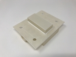
1 "Battery Compartment.stl".
8 "Bolt, 8 by 1.25mm.stl" (use the extra 4 bolts to plug the front and rear deck holes in the hull).
1 "Cover Flat.stl".
1 "Deck.stl".
2 "Hull.stl".
2 "Paddle.stl".
2 "Splash Guard.stl".
For the detailed model, I printed the following parts:
1 "Battery Compartment.stl".
8 "Bolt, 8 by 1.25mm.stl".
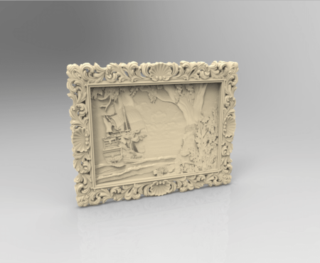
1 "Cover Detailed.stl".
2 "Deck Front.stl" (this component is for both the front and back of WiFi Paddle Boat).
1 "Deck.stl".
2 "Hull.stl".
2 "Paddle.stl".
2 "Splash Guard.stl".
2 "Stack.stl".
For the dual extrusion detailed model, I printed the following parts:
1 "Battery Compartment.stl".
8 "Bolt, 8 by 1.25mm.stl".
1 "Cover Detailed, Ultimaker.3mf" ("Cover Detailed.3mf" excludes the Ultimaker Robot).
2 "Deck Front.3mf" (this component is for both the front and back of WiFi Paddle Boat).
1 "Deck.stl".
1 "Hull Left.3mf".
1 "Hull Right.3mf".
2 "Paddle.stl".
2 "Splash Guard.stl".
2 "Stack.stl".
Prior to assembly, test fit and trim, file, sand, etc. all parts as necessary for smooth movement of moving surfaces, and tight fit for non-moving surfaces. Depending on the colors you chose and your printer settings, more or less trimming, filing and/or sanding may be required. Carefully file all edges that contacted the build plate to make absolutely sure that all build plate "ooze" is removed and that all edges are smooth. I used small jewelers files and plenty of patience to perform this step. All model versions use threaded assembly (8 by 1.25mm) thus an 8 by 1.25mm tap and die may be needed to clean the threaded components.
Regarding the hulls, after printing completely insert the 8 bolts into the threaded holes on the top of the hulls, submerse each hull under water for about a minute, remove, dry off and shake to see if any water has leaked into the hull. If so, spray a few lite coats of clear PLA safe spray paint onto the hull, allow to dry, and test again.
Finally, regarding "Paddle.stl". I've included the file "Paddle Axle Test v1.f3d", the Autodesk Fusion 360 Paddle model with a test paddle axle. I recommend starting this project by printing "Paddle Test.stl" and test fitting both the gear motor axle and 10 by 15 by 4mm sealed bearings to it. The gear motor axle should easily slide into the flatted hole in the paddle test axle, and the bearings should very tightly fit on the paddle test axle. If either of these fits are not correct, you can either try a different color, adjust the X, Y scale of the part in your slicer, or edit the paddle test and paddle using Autodesk Fusion 360 until the part fits correctly.
Program the Heltec Kit 32 Wifi>/b>
WiFi Paddle Boat was written in the Arduino environment for the ESP32 chip. There are numerous excellent tutorials around the web detailing the use of the Arduino environment, therefore I won't duplicate them here. Yet at the time I published this model, some two years after the release of ESP32 based circuit boards, there is surprisingly little information and libraries available for the ESP32 chip. For example, there is no ESP8266 "analogWrite()" function on the ESP32, but there is the ESP32 function "ledcWrite()" which, I presume, was designed for brightness control for an led, so I used this function for the PWM drive of the motor speed controller.
Regarding the WiFi Paddle Boat web page, I used an html "canvas" element for the graphics, and the canvas events "touchstart", "touchmove" and "touchend" for control. I'm of the belief the software should work on touch enabled devices other than iOS, but have not been able to confirm that it will.
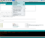
With the Heltec Wifi Kit 32 connected to your computer via a USB cable, open the Arduino environment and load the file "WiFiPaddleBoat.ino". At the top of the file there are a series of include files (files ending in ".h"). Make sure you have the library associated with each of these include files installed in your Arduino environment.
WiFi Paddle Boat operates in access point mode (this mode is similar to the various small sport cameras) in that you connect your smart phone wifi directly to WiFi Paddle Boat wifi. I programmed "WiFiPaddleBoat" with the ssid "WiFiPaddleBoat", password of "WiFiPaddleBoat", and IP address of "192.168.20.20". Before compiling and downloading the software to the WiFi Kit 32, you may wish to change these parameters to suit your needs.
After all libraries are installed and the ssid, password and ip address are set, compile and download the software to the WiFiKit 32. Once downloaded, the WiFi Kit 32 OLED should display the title, copyright, and finally the AP name and IP address. Go to the wifi settings on your smart phone and log onto the WiFi Kit 32 access point ssid using the password. When the wifi connection is complete, open a web browser on your smart phone and navigate to the ip address. If successful, a flashing "stop sign" styled image should appear on the middle of the WiFi Kit 32 OLED, and a blue dot should appear on your smart phone display. If you drag the blue dot to the top of the display, an up arrow should appear along with two power level indicators on the WiFi Kit 32 OLED. Drag the blue dot around the smart phone display and examine the OLED response.
Wiring.
While designing a motor speed controller for this model, I came across the Timesetl L298N Motor Drive Controller which, given it's features and price, I could not justify my design given the cost of a printed circuit board and the individual components required to populate it. So I purchased a five pack of these boards for $14.00 USD, thus each individual board is $2.80 USD. This motor speed controller is designed for much heavier loads than required for WiFi Paddle Boat, so current draw and heat dissipation became a non-issue.
To connect the motor speed controller to the motors and WiFi Kit 32, I performed the following steps.
The port (left) motor is connected to the motor speed controller OUT4 ("+") and OUT3 ("-") screw terminals. Solder a 100mm length of AWG 26 red wire to the port motor "+" terminal, and a 100mm length of AWG 26 black wire to the port motor "-" terminal. Tin the free ends of these wires, then connect the tinned free end of the red wire to motor speed controller OUT4 terminal, and the tinned free end of the black wire to the OUT3 terminal.
The starboard (right) motor is connected to the motor speed controller OUT1 ("+") and OUT2 ("-") screw terminals. Solder a 100mm length of AWG 26 red wire to the starboard motor "+" terminal, and a 100mm length of AWG 26 black wire to the starboard motor "-" terminal. Tin the free ends of these wires, then connect the tinned free end of the red wire to motor speed controller OUT1 terminal, and the tinned free end of the black wire to the OUT2 terminal.
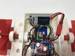
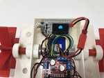
On the motor speed controller board, the 6 pin header styled connector provides the motor control interface. I used a 6 pin Arduino styled female header connector and soldered the control wires between this header connector and the Heltec WiFi Kit 32 as follows:
Solder a 100mm length of AWG 26 green wire between pin 26 on the WiFi Kit 32 and the ENA header pin on the motor speed controller header.
Solder a 100mm length of AWG 26 blue wire between pin 12 on the WiFi Kit 32 and the IN1 header pin on the motor speed controller header.
Solder a 100mm length of AWG 26 yellow wire between pin 13 on the WiFi Kit 32 and the IN2 header pin on the motor speed controller header.
Solder a 100mm length of AWG 26 blue wire between pin 27 on the WiFi Kit 32 and the IN3 header pin on the motor speed controller header.
Solder a 100mm length of AWG 26 yellow wire between pin 14 on the WiFi Kit 32 and the IN4 header pin on the motor speed controller header.
Solder a 100mm length of AWG 26 green wire between pin 25 on the WiFi Kit 32 and the ENB header pin on the motor speed controller header.
The motor speed controller also provides regulated 5vdc on the 3 pin screw terminal which I used to power the WiFi Kit 32. To connect power from the motor speed controller to the WiFi Kit 32, solder a 100mm length of AWG 26 red wire to the WiFi Kit 32 5V pin. Next, solder a 100mm length of AWG 26 black wire to the WiFi Kit 32 GND pin. Tin the free ends of both wires, then connect the tinned free end of the red wire to the motor speed controller +5V pin on the 3 pin screw connector, and connect the tinned free end of the black wire to the motor speed controller GND pin on the 3 pin screw connector.
The entire circuit is powered by a 7.4vdc 1200ma LiPo battery. To connect the battery to the motor speed controller, attach the JST female connector red wire to the motor speed controller +12V pin on the 3 pin screw terminal, and the JST female connector black wire to the GND pin on the 3 pin screw terminal (this terminal shares grounds with the WiFi Kit 32 ground).
Double check all wiring.
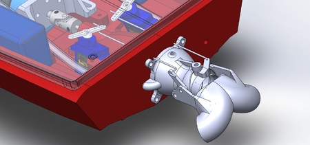
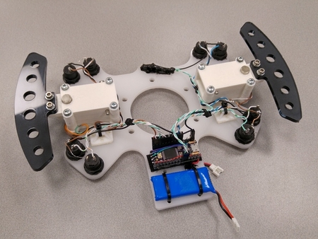
Assembly
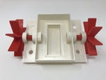
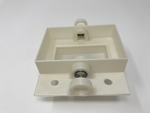
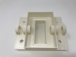
Using 4 small dots of thick cyanoacrylate, glue "Battery Compartment.stl" to "Deck.stl" as shown. Next, using acrylic caulk, seal the underside of the battery compartment to the deck as shown.
Press one bearing into the inner bearing mount in the deck as shown. This should be a very tight fit. If not, you may need to secure the bearing in place using very small dots of thick cyanoacrylate on the outer bearing race, making sure you do not get the cyanoacrylate on the bearing seal or inner race. Repeat with the other side.
Press the two remaining bearings onto the two "Paddle.stl" components. This should be a very tight fit.
Press the paddle assemblies into position. This should be a very tight fit.
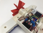
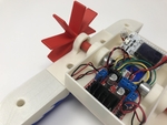
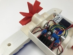
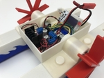
Press the motors into their positions in the deck as shown, making sure the motor shaft flat aligns with the paddle axle flat. This should be a very tight fit.
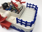
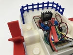
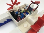
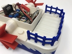
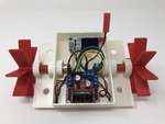
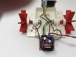
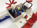
Place the motor speed controller and WiFi Kit 32 into position as shown. Lift the WiFi Kit 32 slightly up, then slide the battery into the battery compartment.
Plug the battery into the motor speed controller and check for proper display operation.
Apply a bead of silicon caulk around the 4 threaded holes in each hull.
Secure the left and right hulls and splash guards to the deck as shown using 4 "Bolt, 8 by 1.25mm.stl".
If you printed "Deck Front.stl" or "Deck Front.3mf", secure the two decks to the hulls as shown using the remaining 4 bolts. If not, simply install the 4 bolts.
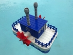
If you printed a detailed cover, then thread the two "Stack.stl" into the cover.
Test.
With assembly complete and before the first water test, I perform the following tasks:
Place WiFi Paddle Boat on a flat surface.
Plug in the battery.
Connect a wifi enabled device to the WiFi Paddle Boat wifi (my WiFi Paddle Boat ssid is "WiFiPaddleBoat").
Open a web browser on a wifi enabled device.
Navigate to the WiFi Paddle Boat ip address (my WiFi Paddle Boat ip address is 192.168.20.20).
When the blue dot appears on the web browser, a "stop sign" style image appears flashing on the WiFi Kit 32 OLED. Drag the dot to the top center of the display and the OLED display shows an up arrow and 2 power level indicators (one for the port motor, and a second for the starboard motor). Make sure the paddles are turning in the correct direction. Move the dot to the bottom center of the display and watch for proper OLED indications and paddle movement.
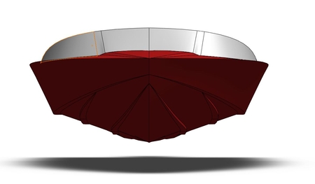
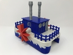
With that complete, place the cover you chose over the electronics bay in the deck, place WiFi Paddle Boat in the water, and off you go!
That's how I printed, programmed, wired and assembled WiFi Paddle Boat.
Hope you enjoy it!
Designer
Greg Zumwalt3d model description
A WiFi enabled remote controlled Paddle BoatSummer is in full swing in Oklahoma and the kids, grandkids, nieces, nephews and, well, just about e...veryone we know is in Lake Zumwalt to cool down. My wife has purchased enough pool toys to fill Lake Zumwalt, so I figured I would join the pool toy fray with WiFi Paddle Boat.
WiFi Paddle Boat is a paddle boat controlled via wifi using a smart phone, tablet or other touch enabled device. WiFi Paddle Boat creates a wifi access point (much like the small sport cameras) that you connect to via your wifi enabled device wifi settings. Then, using your wifi touch enabled device web browser, you simply navigate to the WiFi Paddle Boat web page and off you go! The controls for WiFi Paddle Boat are identical to those of my "Lady Buggy" and "Santa Sleigh" designs so it's easy for the grandkids to operate.
A word of caution; I designed WiFi Paddle Boat to be "splash resistant" not "water proof", so if a rogue wave, grandchild, niece, nephew, etc., "submarines" WiFi Paddle Boat, well good luck.
As usual, I probably forgot a file or two or who knows what else, so if you have any questions, please do not hesitate to ask as I do make mistakes in plenty.
Designed using Autodesk Fusion 360, sliced using Cura 3.4.1, and printed in PLA on both and Ultimaker 2+ Extended and an Ultimaker 3 Extended.
3d model print parameters
Purchase, Print and Prepare the Parts.Before you begin, note that WiFi Paddle Boat contains large, flat components that may not fit your build are...a and if they do, warping can become a significant issue so use a brim and your best techniques for build plate adhesion. Note also that there are some thin walled components, some as thin as .8mm, so before printing test each part using your slicer in layer mode to confirm your printers ability to print the parts. And finally, the design requires that the motors, bearings and paddles must align on axis as accurately as possible, so print "Deck.stl" with supports at your highest resolution, then be prepared to carefully file the bearing mounts for a smooth, round, yet friction fit surface.
I purchased the following parts for WiFi Paddle Boat:
1 Heltec WiFi Kit 32 with Oled display (on line).
1 Timesetl L298N Motor Drive Controller (on line).
2 300 RPM 6 VDC Mini Gear Motors (on line).
4 10 by 15 by 4mm sealed ball bearings (I used a ProtekRC PTK-10046, local hobby shop).
1 Ares AZSZ2503 1200 mAh 2-Cell/2S 7.4V 25C Lipo Battery (local hobby shop).
JST Female Connector (sized for battery, local hobby shop).
You will also need cyanoacrylate glue, acrylic caulk, needle nose pliers and assorted precision hand tools, jewelers files, wire cutters, wire strippers, solder and soldering iron, and maybe clear PLA safe spray paint.
I printed "Deck.stl" and "Bolt, 8 by 1.25mm.stl" at .15mm layer height, and the remaining parts at .2mm layer height (the .2mm layer height added a "crusty" look (?) to the remaining components which, to me at least, simulated years of over painting, in addition they printed in much less time). I printed "Bolt, 8 by 1.25.stl" at 50% infill, the remaining parts at 20% infill. I printed "Deck.stl" with supports, the remaining parts with no supports.
I've included a few printing options for WiFi Paddle Boat. The base model is the simplest and contains the fewest parts. The detailed model has the details available in the detailed dual extrusion model but for single extrusion. The detailed dual extrusion model is for dual extrusion printers and has the same details as the detailed model.
For the base model, I printed the following parts:
1 "Battery Compartment.stl".
8 "Bolt, 8 by 1.25mm.stl" (use the extra 4 bolts to plug the front and rear deck holes in the hull).
1 "Cover Flat.stl".
1 "Deck.stl".
2 "Hull.stl".
2 "Paddle.stl".
2 "Splash Guard.stl".
For the detailed model, I printed the following parts:
1 "Battery Compartment.stl".
8 "Bolt, 8 by 1.25mm.stl".
1 "Cover Detailed.stl".
2 "Deck Front.stl" (this component is for both the front and back of WiFi Paddle Boat).
1 "Deck.stl".
2 "Hull.stl".
2 "Paddle.stl".
2 "Splash Guard.stl".
2 "Stack.stl".
For the dual extrusion detailed model, I printed the following parts:
1 "Battery Compartment.stl".
8 "Bolt, 8 by 1.25mm.stl".
1 "Cover Detailed, Ultimaker.3mf" ("Cover Detailed.3mf" excludes the Ultimaker Robot).
2 "Deck Front.3mf" (this component is for both the front and back of WiFi Paddle Boat).
1 "Deck.stl".
1 "Hull Left.3mf".
1 "Hull Right.3mf".
2 "Paddle.stl".
2 "Splash Guard.stl".
2 "Stack.stl".
Prior to assembly, test fit and trim, file, sand, etc. all parts as necessary for smooth movement of moving surfaces, and tight fit for non-moving surfaces. Depending on the colors you chose and your printer settings, more or less trimming, filing and/or sanding may be required. Carefully file all edges that contacted the build plate to make absolutely sure that all build plate "ooze" is removed and that all edges are smooth. I used small jewelers files and plenty of patience to perform this step. All model versions use threaded assembly (8 by 1.25mm) thus an 8 by 1.25mm tap and die may be needed to clean the threaded components.
Regarding the hulls, after printing completely insert the 8 bolts into the threaded holes on the top of the hulls, submerse each hull under water for about a minute, remove, dry off and shake to see if any water has leaked into the hull. If so, spray a few lite coats of clear PLA safe spray paint onto the hull, allow to dry, and test again.
Finally, regarding "Paddle.stl". I've included the file "Paddle Axle Test v1.f3d", the Autodesk Fusion 360 Paddle model with a test paddle axle. I recommend starting this project by printing "Paddle Test.stl" and test fitting both the gear motor axle and 10 by 15 by 4mm sealed bearings to it. The gear motor axle should easily slide into the flatted hole in the paddle test axle, and the bearings should very tightly fit on the paddle test axle. If either of these fits are not correct, you can either try a different color, adjust the X, Y scale of the part in your slicer, or edit the paddle test and paddle using Autodesk Fusion 360 until the part fits correctly.
Program the Heltec Kit 32 Wifi>/b>
WiFi Paddle Boat was written in the Arduino environment for the ESP32 chip. There are numerous excellent tutorials around the web detailing the use of the Arduino environment, therefore I won't duplicate them here. Yet at the time I published this model, some two years after the release of ESP32 based circuit boards, there is surprisingly little information and libraries available for the ESP32 chip. For example, there is no ESP8266 "analogWrite()" function on the ESP32, but there is the ESP32 function "ledcWrite()" which, I presume, was designed for brightness control for an led, so I used this function for the PWM drive of the motor speed controller.
Regarding the WiFi Paddle Boat web page, I used an html "canvas" element for the graphics, and the canvas events "touchstart", "touchmove" and "touchend" for control. I'm of the belief the software should work on touch enabled devices other than iOS, but have not been able to confirm that it will.
With the Heltec Wifi Kit 32 connected to your computer via a USB cable, open the Arduino environment and load the file "WiFiPaddleBoat.ino". At the top of the file there are a series of include files (files ending in ".h"). Make sure you have the library associated with each of these include files installed in your Arduino environment.
WiFi Paddle Boat operates in access point mode (this mode is similar to the various small sport cameras) in that you connect your smart phone wifi directly to WiFi Paddle Boat wifi. I programmed "WiFiPaddleBoat" with the ssid "WiFiPaddleBoat", password of "WiFiPaddleBoat", and IP address of "192.168.20.20". Before compiling and downloading the software to the WiFi Kit 32, you may wish to change these parameters to suit your needs.
After all libraries are installed and the ssid, password and ip address are set, compile and download the software to the WiFiKit 32. Once downloaded, the WiFi Kit 32 OLED should display the title, copyright, and finally the AP name and IP address. Go to the wifi settings on your smart phone and log onto the WiFi Kit 32 access point ssid using the password. When the wifi connection is complete, open a web browser on your smart phone and navigate to the ip address. If successful, a flashing "stop sign" styled image should appear on the middle of the WiFi Kit 32 OLED, and a blue dot should appear on your smart phone display. If you drag the blue dot to the top of the display, an up arrow should appear along with two power level indicators on the WiFi Kit 32 OLED. Drag the blue dot around the smart phone display and examine the OLED response.
Wiring.
While designing a motor speed controller for this model, I came across the Timesetl L298N Motor Drive Controller which, given it's features and price, I could not justify my design given the cost of a printed circuit board and the individual components required to populate it. So I purchased a five pack of these boards for $14.00 USD, thus each individual board is $2.80 USD. This motor speed controller is designed for much heavier loads than required for WiFi Paddle Boat, so current draw and heat dissipation became a non-issue.
To connect the motor speed controller to the motors and WiFi Kit 32, I performed the following steps.
The port (left) motor is connected to the motor speed controller OUT4 ("+") and OUT3 ("-") screw terminals. Solder a 100mm length of AWG 26 red wire to the port motor "+" terminal, and a 100mm length of AWG 26 black wire to the port motor "-" terminal. Tin the free ends of these wires, then connect the tinned free end of the red wire to motor speed controller OUT4 terminal, and the tinned free end of the black wire to the OUT3 terminal.
The starboard (right) motor is connected to the motor speed controller OUT1 ("+") and OUT2 ("-") screw terminals. Solder a 100mm length of AWG 26 red wire to the starboard motor "+" terminal, and a 100mm length of AWG 26 black wire to the starboard motor "-" terminal. Tin the free ends of these wires, then connect the tinned free end of the red wire to motor speed controller OUT1 terminal, and the tinned free end of the black wire to the OUT2 terminal.
On the motor speed controller board, the 6 pin header styled connector provides the motor control interface. I used a 6 pin Arduino styled female header connector and soldered the control wires between this header connector and the Heltec WiFi Kit 32 as follows:
Solder a 100mm length of AWG 26 green wire between pin 26 on the WiFi Kit 32 and the ENA header pin on the motor speed controller header.
Solder a 100mm length of AWG 26 blue wire between pin 12 on the WiFi Kit 32 and the IN1 header pin on the motor speed controller header.
Solder a 100mm length of AWG 26 yellow wire between pin 13 on the WiFi Kit 32 and the IN2 header pin on the motor speed controller header.
Solder a 100mm length of AWG 26 blue wire between pin 27 on the WiFi Kit 32 and the IN3 header pin on the motor speed controller header.
Solder a 100mm length of AWG 26 yellow wire between pin 14 on the WiFi Kit 32 and the IN4 header pin on the motor speed controller header.
Solder a 100mm length of AWG 26 green wire between pin 25 on the WiFi Kit 32 and the ENB header pin on the motor speed controller header.
The motor speed controller also provides regulated 5vdc on the 3 pin screw terminal which I used to power the WiFi Kit 32. To connect power from the motor speed controller to the WiFi Kit 32, solder a 100mm length of AWG 26 red wire to the WiFi Kit 32 5V pin. Next, solder a 100mm length of AWG 26 black wire to the WiFi Kit 32 GND pin. Tin the free ends of both wires, then connect the tinned free end of the red wire to the motor speed controller +5V pin on the 3 pin screw connector, and connect the tinned free end of the black wire to the motor speed controller GND pin on the 3 pin screw connector.
The entire circuit is powered by a 7.4vdc 1200ma LiPo battery. To connect the battery to the motor speed controller, attach the JST female connector red wire to the motor speed controller +12V pin on the 3 pin screw terminal, and the JST female connector black wire to the GND pin on the 3 pin screw terminal (this terminal shares grounds with the WiFi Kit 32 ground).
Double check all wiring.
Assembly
Using 4 small dots of thick cyanoacrylate, glue "Battery Compartment.stl" to "Deck.stl" as shown. Next, using acrylic caulk, seal the underside of the battery compartment to the deck as shown.
Press one bearing into the inner bearing mount in the deck as shown. This should be a very tight fit. If not, you may need to secure the bearing in place using very small dots of thick cyanoacrylate on the outer bearing race, making sure you do not get the cyanoacrylate on the bearing seal or inner race. Repeat with the other side.
Press the two remaining bearings onto the two "Paddle.stl" components. This should be a very tight fit.
Press the paddle assemblies into position. This should be a very tight fit.
Press the motors into their positions in the deck as shown, making sure the motor shaft flat aligns with the paddle axle flat. This should be a very tight fit.
Place the motor speed controller and WiFi Kit 32 into position as shown. Lift the WiFi Kit 32 slightly up, then slide the battery into the battery compartment.
Plug the battery into the motor speed controller and check for proper display operation.
Apply a bead of silicon caulk around the 4 threaded holes in each hull.
Secure the left and right hulls and splash guards to the deck as shown using 4 "Bolt, 8 by 1.25mm.stl".
If you printed "Deck Front.stl" or "Deck Front.3mf", secure the two decks to the hulls as shown using the remaining 4 bolts. If not, simply install the 4 bolts.
If you printed a detailed cover, then thread the two "Stack.stl" into the cover.
Test.
With assembly complete and before the first water test, I perform the following tasks:
Place WiFi Paddle Boat on a flat surface.
Plug in the battery.
Connect a wifi enabled device to the WiFi Paddle Boat wifi (my WiFi Paddle Boat ssid is "WiFiPaddleBoat").
Open a web browser on a wifi enabled device.
Navigate to the WiFi Paddle Boat ip address (my WiFi Paddle Boat ip address is 192.168.20.20).
When the blue dot appears on the web browser, a "stop sign" style image appears flashing on the WiFi Kit 32 OLED. Drag the dot to the top center of the display and the OLED display shows an up arrow and 2 power level indicators (one for the port motor, and a second for the starboard motor). Make sure the paddles are turning in the correct direction. Move the dot to the bottom center of the display and watch for proper OLED indications and paddle movement.
With that complete, place the cover you chose over the electronics bay in the deck, place WiFi Paddle Boat in the water, and off you go!
That's how I printed, programmed, wired and assembled WiFi Paddle Boat.
Hope you enjoy it!