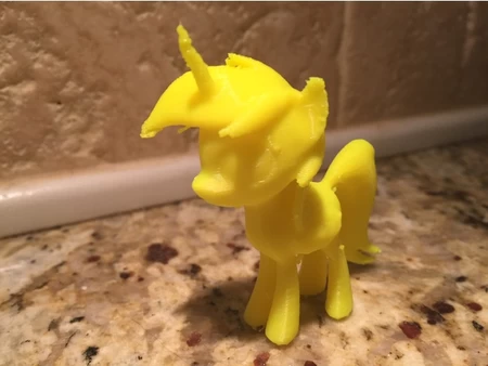
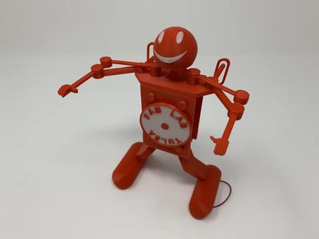
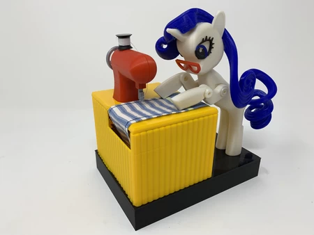
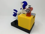
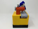
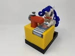
"rarity", a 3d printed automaton 3D for print


7008 Views 1 Likes 0 Downloads Download the piece here from 3dforprint
https://youtu.be/P9ws9W3nZrs
A waitress at our favorite sushi restaurant fell in love with a morisato54 (YouTube) automat...on featuring the "My Little Pony" character "Rarity", and asked if I could design, 3D print and assemble a reproduction of the model, so this is my first attempt at her challenge.
As those who follow me know, I'm not an artist, and this model was a challenge for me, especially the hair and tail features. The hair feature I finally decided to print in two pieces on my Ultimaker S5 using PVA for support. My sewing skills are equally challenged, so my wonderful wife stepped in to sew the test fabric that appears in the video, as well as selecting the various colors for the model.
As usual I probably forgot a file or two or who knows what else, so if you have any questions, please do not hesitate to ask as I do make plenty of mistakes.
Designed using Autodesk Fusion 360, sliced using Cura 4.6.1, and 3D printed in PLA on an Ultimaker 2+ Extended, an Ultimaker 3 Extended and an Ultimaker S5.
I acquired the following parts:
• Ten 6mm (diameter) by 1.5mm (thick) neodymium magnets (local hobby shop).
• Six 3mm (diameter) by ...1.5mm (thick) neodymium magnets (local hobby shop).
• One N20 6VDC 100RPM gear motor (on line).
• One R07 O-Ring (10mm ID, 2.5mm section, my personal O-Ring stash).
• One O-RIng (1 7/8" ID, 3/32" section, plumbing supply store).
• One AAA quad battery holder with switch (on line).
I 3D printed all parts as noted in the attached file "Parts.pdf".
This mechanism is a high precision print and assembly using at times very small precision 3D printed parts in confined spaces with highly precise alignment. I printed the gears, levers, arms, cams and wheels using the Ultimaker Cura 4.6.1 "Engineering Profile" on my Ultimaker S5, which provides a highly accurate tolerance requiring minimal if any trimming, filing, drilling or sanding. However, prior to assembly, I still test fitted and trimmed, filed, drilled, sanded, etc. all parts as necessary for smooth movement of moving surfaces, and tight fit for non moving surfaces. Depending on your slicer, printer, printer settings and the colors you chose, more or less trimming, filing, drilling and/or sanding may be required to successfully recreate this model. I carefully filed all edges that contacted the build plate to make absolutely certain that all build plate "ooze" is removed and that all edges are smooth using small jewelers files and plenty of patience to perform this step.
This mechanism also uses threaded assembly, so I used a tap and die set (6mm by 1) as required for thread cleaning.
Sewing Machine Pre-Assembly.
For pre-assembly of the sewing machine, I:
• Pressed "Sewing Machine, Pin, Axle.stl" into the hole in "Sewing Machine, Axle.stl".
• Pressed "Sewing Machine, Pulley.stl" onto the axle assembly.
• Threaded "Sewing Machine, Wheel.stl" onto the axle assembly.
• Placed the axle assembly into "Sewing Machine, Housing, Rear.stl", aligned the pulley with thread spool mounting pin, made sure the pulley was perpendicular to the axle, then secured the pulley in place with a small dot of glue.
• Placed "Sewing Machine, Needle.stl" over the axle assembly pin and positioned it in the rear housing.
• Placed "Sewing Machine, Housing, Front.stl" over the assembly, and secured in place with "Thread Spool.stl".
• Rotated the axle via the axle wheel to make certain the axle rotated freely.
Sewing Machine Assembly.
For sewing machine table assembly, I:
• Positioned "Pulley, Axle, Main.stl" and the large O-Ring over the opening in "Sewing Machine, Table.stl".
• Slid "Axle, Main (1.5m 20t).stl" through the hole in the table main axle tower, then through the pulley and O-Ring.
• Pressed "Gear, Axle, Main.stl" onto the end of the main axle assembly.
• Tested the main axle assembly to make sure it rotated freely, then secured the main axle gear to the axle using a small dot of glue.
• Pressed the gear motor into the table assembly.
• Pressed "Gear, Motor.stl" onto the gear motor output shaft.
• Pressed eight 6mm magnets into "Magnet, Mount.stl", four in each cup, with matching polarity.
• Positioned the magnet mount assembly on the table assembly magnet mount pin.
• Secured the magnet mount assembly to the table assembly using "Nut, Magnet Mount.stl"
• Tested the magnet mount assembly for free movement.
• Threaded "Axle, Magnet Mount.stl" into the magnet mount assembly.
• Positioned slide "Pin, Axle, Magnet Mount.stl" into the non-threaded hole in "Wheel, Magnet Mount.stl", then slide the hole in the Pin, Axle, Magnet Mount over Axle, Magnet Mount then secured the wheel to the table assembly using "Gear, Magnet Mount (1.5m 20t).stl".
• Wrapped one layer of transparent tape around the center of the smaller axle on "Roller.stl".
• Positioned the roller assembly into the table assembly as shown, then secured in place with "Bushing, Roller.stl" and "Gear, Axle, Roller.stl".
• Positioned "Cam, Arm, Yoke.stl" then secured in place with "Gear, Arm, Yoke (1.5m 20t).stl".
• Tested the assembly for free movement.
• Positioned the large O-Ring around the main axle pulley and sewing machine axle pulley.
• Positioned the axle assembly into the rear housing.
• Positioned the needle around the axle pin and into the rear housing.
• Positioned the sewing machine front housing over the assembly.
• Secured the housings together with the thread spool.
• Positioned the sewing machine assembly into the table sewing machine opening.
• Applied power to the motor and adjusted the sewing machine vertically to the point where the sewing machine operated with minimal tension on the O-Ring, then secured the sewing machine to the table using small dots of glue.
• My wife sewed cut a strip of fabric 9.5" long by 1 5/8" wide, then formed a loop by sewing the ends together with a 1/2" overlap. I slid the material loop into position on the table.
Rarity Assembly.
For Rarity assembly, I:
• Glued "Eye, Lash, Left.stl", "Eye, Blue, Left.stl" and "Eye, Black, Left.stl" to the left side of "Head.stl".
• Glued "Eye, Lash, Right.stl", "Eye, Blue, Right.stl" and "Eye, Black, Right.stl" to the right side of the head assembly.
• Glued "Hair, Back.stl" and "Hair, Front.stl" to the head assembly.
• Pressed "Arm, Head.stl" into the head assembly.
• Pressed one 6mm magnet into the magnet hole in the arm.
• Glued "Glasses.stl" to the head assembly.
• Glued "Tail.stl" to "Body.stl".
• Attached "Arm, Upper, Left.stl" to the body assembly using "Axle, Arm, Upper, Left.stl".
• Slid the head assembly into the body assembly (this can be tricky), aligned the head arm axle hole with the arm mount hole, then attached the head assembly and "Arm, Upper, Right.stl" to the body assembly using "Axle, Arm, Upper Right.stl".
• Attached "Arm, Lower, Left.stl" to the left upper arm using one "Axle, Arm, Lower.stl".
• Attached "Arm, Lower, Right.stl" to the right upper arm using the remaining "Axle, Arm, Lower.stl".
• Tested to make absolutely certain the upper and lower arm joints and head rotated freely.
• Pressed six 3mm magnets, three each into each lower arm matching the polarity of the magnet mount magnets.
Final Assembly.
For final assembly, I:
• Soldered the battery pack wires to the motor such that the material was pulled as shown in the video.
• Wrapped thread around the thread holder securing in place with small dots of glue, then glued the free end to the head of the needle.
• Pressed the Rarity into "Base.stl" (this will be adjusted and secured later).
• Placed the smaller O-Ring on "Wheel, O Ring.stl".
• Positioned the wheel assembly into "Wheel, O Ring Carriage.stl".
• Secured the wheel assembly to the carriage using "Wheel, O Ring Axle.stl".
• Secured the carriage assembly to the base assembly using two "Bolt.stl".
• Pressed one 6mm magnet into "Yoke.stl".
• Slid the yoke assembly, magnet end first, into the left leg of the body until it attached to the magnet in the head arm.
• Slid "Sewing Machine Table Skirt.stl" over the table assembly.
• Attached the table assembly to the base assembly using four "Bolt.stl".
• Attached "Arm, Yoke.stl" to the base assembly using "Axle, Arm, Yoke.stl".
• Slid the hole in the yoke assembly over the pin in the yoke arm.
• Attached the battery pack to the underside of the base assembly using double sided tape.
• Applied power to the assembly, then adjusted both the pitch and roll of Rarity until arm movement was attained, then glued Rarity to the base.
And that is how I 3D printed and assembled "Rarity, a 3D Printed Automaton".
Hope you enjoyed it!
Designer
Greg Zumwalt3d model description
A challenge from a friend.https://youtu.be/P9ws9W3nZrs
A waitress at our favorite sushi restaurant fell in love with a morisato54 (YouTube) automat...on featuring the "My Little Pony" character "Rarity", and asked if I could design, 3D print and assemble a reproduction of the model, so this is my first attempt at her challenge.
As those who follow me know, I'm not an artist, and this model was a challenge for me, especially the hair and tail features. The hair feature I finally decided to print in two pieces on my Ultimaker S5 using PVA for support. My sewing skills are equally challenged, so my wonderful wife stepped in to sew the test fabric that appears in the video, as well as selecting the various colors for the model.
As usual I probably forgot a file or two or who knows what else, so if you have any questions, please do not hesitate to ask as I do make plenty of mistakes.
Designed using Autodesk Fusion 360, sliced using Cura 4.6.1, and 3D printed in PLA on an Ultimaker 2+ Extended, an Ultimaker 3 Extended and an Ultimaker S5.
3d model print parameters
Parts.I acquired the following parts:
• Ten 6mm (diameter) by 1.5mm (thick) neodymium magnets (local hobby shop).
• Six 3mm (diameter) by ...1.5mm (thick) neodymium magnets (local hobby shop).
• One N20 6VDC 100RPM gear motor (on line).
• One R07 O-Ring (10mm ID, 2.5mm section, my personal O-Ring stash).
• One O-RIng (1 7/8" ID, 3/32" section, plumbing supply store).
• One AAA quad battery holder with switch (on line).
I 3D printed all parts as noted in the attached file "Parts.pdf".
This mechanism is a high precision print and assembly using at times very small precision 3D printed parts in confined spaces with highly precise alignment. I printed the gears, levers, arms, cams and wheels using the Ultimaker Cura 4.6.1 "Engineering Profile" on my Ultimaker S5, which provides a highly accurate tolerance requiring minimal if any trimming, filing, drilling or sanding. However, prior to assembly, I still test fitted and trimmed, filed, drilled, sanded, etc. all parts as necessary for smooth movement of moving surfaces, and tight fit for non moving surfaces. Depending on your slicer, printer, printer settings and the colors you chose, more or less trimming, filing, drilling and/or sanding may be required to successfully recreate this model. I carefully filed all edges that contacted the build plate to make absolutely certain that all build plate "ooze" is removed and that all edges are smooth using small jewelers files and plenty of patience to perform this step.
This mechanism also uses threaded assembly, so I used a tap and die set (6mm by 1) as required for thread cleaning.
Sewing Machine Pre-Assembly.
For pre-assembly of the sewing machine, I:
• Pressed "Sewing Machine, Pin, Axle.stl" into the hole in "Sewing Machine, Axle.stl".
• Pressed "Sewing Machine, Pulley.stl" onto the axle assembly.
• Threaded "Sewing Machine, Wheel.stl" onto the axle assembly.
• Placed the axle assembly into "Sewing Machine, Housing, Rear.stl", aligned the pulley with thread spool mounting pin, made sure the pulley was perpendicular to the axle, then secured the pulley in place with a small dot of glue.
• Placed "Sewing Machine, Needle.stl" over the axle assembly pin and positioned it in the rear housing.
• Placed "Sewing Machine, Housing, Front.stl" over the assembly, and secured in place with "Thread Spool.stl".
• Rotated the axle via the axle wheel to make certain the axle rotated freely.
Sewing Machine Assembly.
For sewing machine table assembly, I:
• Positioned "Pulley, Axle, Main.stl" and the large O-Ring over the opening in "Sewing Machine, Table.stl".
• Slid "Axle, Main (1.5m 20t).stl" through the hole in the table main axle tower, then through the pulley and O-Ring.
• Pressed "Gear, Axle, Main.stl" onto the end of the main axle assembly.
• Tested the main axle assembly to make sure it rotated freely, then secured the main axle gear to the axle using a small dot of glue.
• Pressed the gear motor into the table assembly.
• Pressed "Gear, Motor.stl" onto the gear motor output shaft.
• Pressed eight 6mm magnets into "Magnet, Mount.stl", four in each cup, with matching polarity.
• Positioned the magnet mount assembly on the table assembly magnet mount pin.
• Secured the magnet mount assembly to the table assembly using "Nut, Magnet Mount.stl"
• Tested the magnet mount assembly for free movement.
• Threaded "Axle, Magnet Mount.stl" into the magnet mount assembly.
• Positioned slide "Pin, Axle, Magnet Mount.stl" into the non-threaded hole in "Wheel, Magnet Mount.stl", then slide the hole in the Pin, Axle, Magnet Mount over Axle, Magnet Mount then secured the wheel to the table assembly using "Gear, Magnet Mount (1.5m 20t).stl".
• Wrapped one layer of transparent tape around the center of the smaller axle on "Roller.stl".
• Positioned the roller assembly into the table assembly as shown, then secured in place with "Bushing, Roller.stl" and "Gear, Axle, Roller.stl".
• Positioned "Cam, Arm, Yoke.stl" then secured in place with "Gear, Arm, Yoke (1.5m 20t).stl".
• Tested the assembly for free movement.
• Positioned the large O-Ring around the main axle pulley and sewing machine axle pulley.
• Positioned the axle assembly into the rear housing.
• Positioned the needle around the axle pin and into the rear housing.
• Positioned the sewing machine front housing over the assembly.
• Secured the housings together with the thread spool.
• Positioned the sewing machine assembly into the table sewing machine opening.
• Applied power to the motor and adjusted the sewing machine vertically to the point where the sewing machine operated with minimal tension on the O-Ring, then secured the sewing machine to the table using small dots of glue.
• My wife sewed cut a strip of fabric 9.5" long by 1 5/8" wide, then formed a loop by sewing the ends together with a 1/2" overlap. I slid the material loop into position on the table.
Rarity Assembly.
For Rarity assembly, I:
• Glued "Eye, Lash, Left.stl", "Eye, Blue, Left.stl" and "Eye, Black, Left.stl" to the left side of "Head.stl".
• Glued "Eye, Lash, Right.stl", "Eye, Blue, Right.stl" and "Eye, Black, Right.stl" to the right side of the head assembly.
• Glued "Hair, Back.stl" and "Hair, Front.stl" to the head assembly.
• Pressed "Arm, Head.stl" into the head assembly.
• Pressed one 6mm magnet into the magnet hole in the arm.
• Glued "Glasses.stl" to the head assembly.
• Glued "Tail.stl" to "Body.stl".
• Attached "Arm, Upper, Left.stl" to the body assembly using "Axle, Arm, Upper, Left.stl".
• Slid the head assembly into the body assembly (this can be tricky), aligned the head arm axle hole with the arm mount hole, then attached the head assembly and "Arm, Upper, Right.stl" to the body assembly using "Axle, Arm, Upper Right.stl".
• Attached "Arm, Lower, Left.stl" to the left upper arm using one "Axle, Arm, Lower.stl".
• Attached "Arm, Lower, Right.stl" to the right upper arm using the remaining "Axle, Arm, Lower.stl".
• Tested to make absolutely certain the upper and lower arm joints and head rotated freely.
• Pressed six 3mm magnets, three each into each lower arm matching the polarity of the magnet mount magnets.
Final Assembly.
For final assembly, I:
• Soldered the battery pack wires to the motor such that the material was pulled as shown in the video.
• Wrapped thread around the thread holder securing in place with small dots of glue, then glued the free end to the head of the needle.
• Pressed the Rarity into "Base.stl" (this will be adjusted and secured later).
• Placed the smaller O-Ring on "Wheel, O Ring.stl".
• Positioned the wheel assembly into "Wheel, O Ring Carriage.stl".
• Secured the wheel assembly to the carriage using "Wheel, O Ring Axle.stl".
• Secured the carriage assembly to the base assembly using two "Bolt.stl".
• Pressed one 6mm magnet into "Yoke.stl".
• Slid the yoke assembly, magnet end first, into the left leg of the body until it attached to the magnet in the head arm.
• Slid "Sewing Machine Table Skirt.stl" over the table assembly.
• Attached the table assembly to the base assembly using four "Bolt.stl".
• Attached "Arm, Yoke.stl" to the base assembly using "Axle, Arm, Yoke.stl".
• Slid the hole in the yoke assembly over the pin in the yoke arm.
• Attached the battery pack to the underside of the base assembly using double sided tape.
• Applied power to the assembly, then adjusted both the pitch and roll of Rarity until arm movement was attained, then glued Rarity to the base.
And that is how I 3D printed and assembled "Rarity, a 3D Printed Automaton".
Hope you enjoyed it!